Bitmap2LCD is a tool for programming small Graphic LCDs in embedded systems.
OBSOLETE Article : For older versions
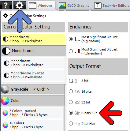
All the configuration settings of the Bitmap2LCD tool have been reorganized and grouped in one single window :
The main settings, the output file header syntax settings, the pixel to data array orientation setting , the optional postprocessing and a new user friendly pixel to data array organisation display.
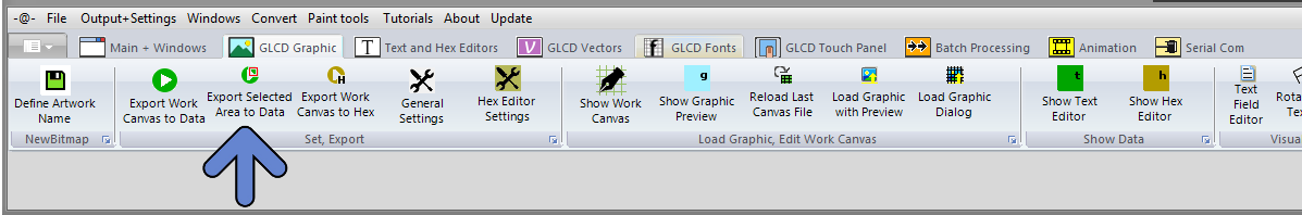
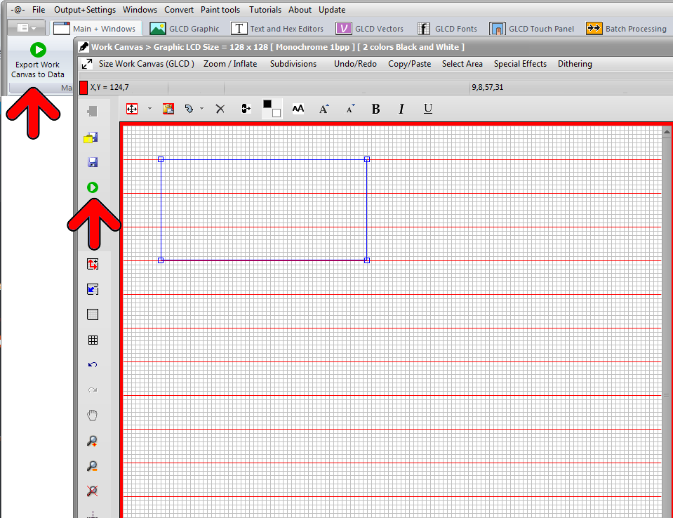
Let’s see how to configure the GLCD data output settings :
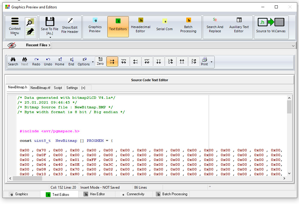
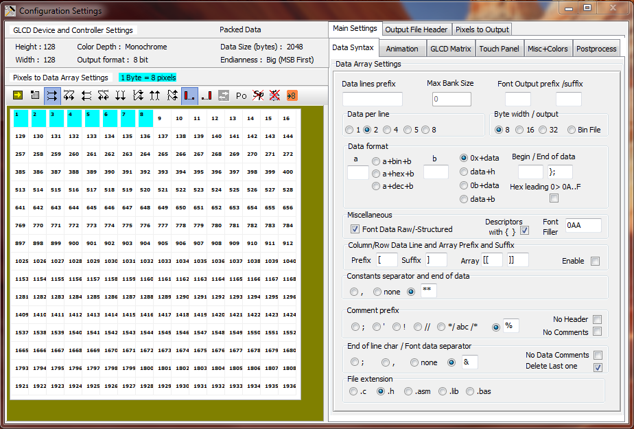
The generated data array file can be configured to meet the syntax requests of your compiler or assembler. There are many possible settings, to make it possible to match the tool with most of the compilers of the market.
At first, you define the table data settings
- Data Width format. ( 8,16 or 32 bits data)
- Binary, Hex or decimal format.
- Syntax of Data Byte/Word (make it compatible with your favorite compiler, assembler)
- Type of file (extension)
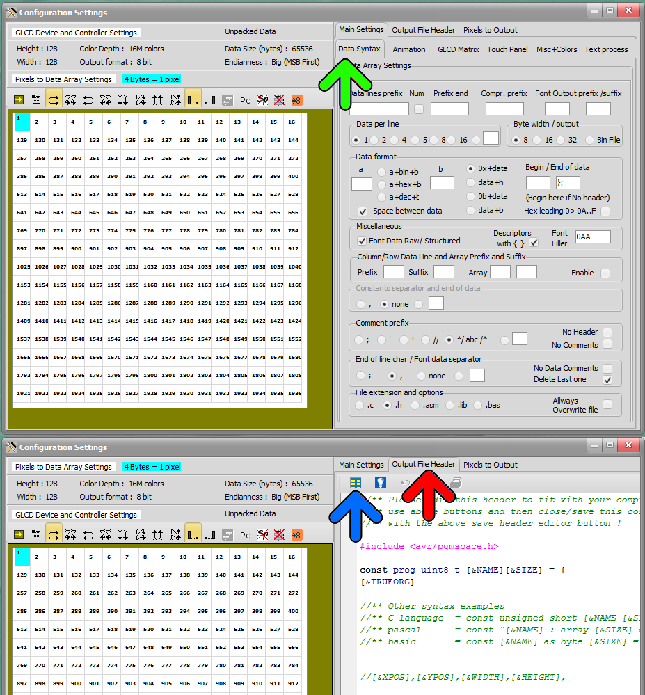
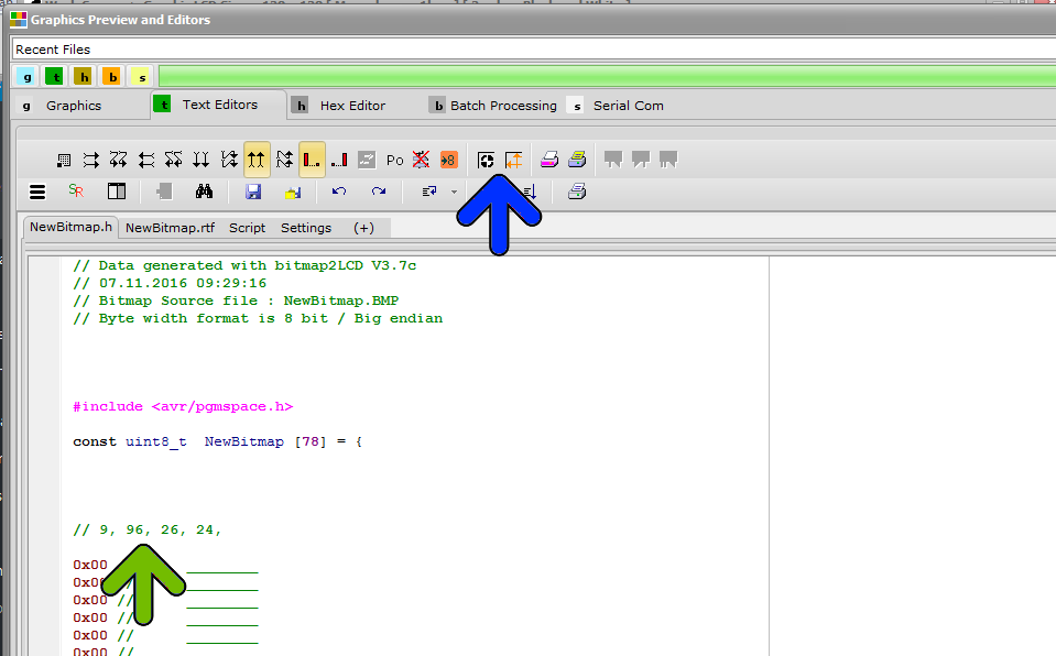
As next, you define the header syntax ( output file header tab)
>> To edit file header blue arrow )
- Click on the edit button and the header script is loaded into the editor. Modify it to meet your requirements.
- When ready, quit the header editor by clicking the same button.
- Find more about the header syntax at the end of this article.
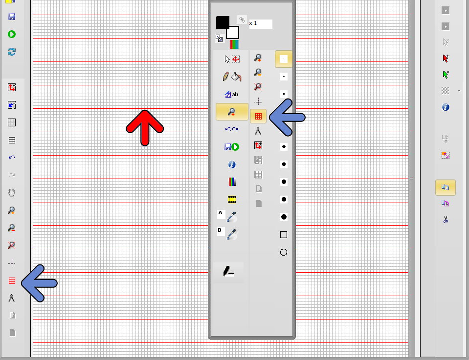
As next, you define the way the data arrays are arranged to correctly fit in the DDRAM of your LCD controller. ( Data orientation ) These settings must be compatible with the LCD display functions in the GLCD Library you use in your project.
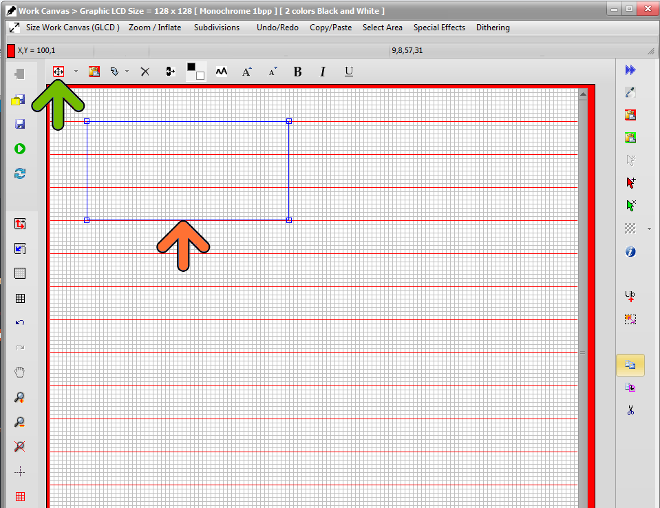
- The origin corner X0,Y0
- Data direction (The direction in which the pixels slices are taken from the work canvas and converted to GLCD data, for example in slices or in full canvas height or full canvas width. A slice is 8 pixels in monochrome mode and 2 pixels in 4bpp grayscale mode)
- The Endianness (Most Significant Bit is first or last)
- Special settings
More about File Header syntax ( output file header tab )
The script components [&***] can be included only once and will be replaced by the data or value when the data array is generated. Not needed script components can be erased.
[&NAME]
The [$NAME] and the image size and position are optional and can be placed optionally anywhere in the header.
[&SIZE]
Same for Size of Data
[&TRUEORG]
This is the script component if present in the file, to indicate that you want to have the XPOS and YPOS origins of a reduced dynamic table of constants ( a part of the display you want to change ) given from the X0,Y0 corner you selected in the table translation manager window.
[&XPOS]
[&YPOS]
[&WIDTH]
[&HEIGHT]
The corner position on the Work Canvas and the size of the converted graphic area can be exported into the file.
There are additional script components for font generation and data compression.