Welcome to Bitmap2LCD !
You can find various TUTORIALS on-line on the Bitmap2LCD BLOG.
https://bitmap2lcd.com/blog
The HELP topics are also easily accessible from inside the
tool, using the internal Web Browser.
Presentation of Bitmap2LCD (Youtube)
Link for versions anterior to V3.7
Getting Started : A short tutorial
Bitmap2LCD is a software tool for programming small Graphic LCDs in embedded systems and a programmable text and graphic processing tool.
How to find information here ?
At the TOP RIGHT HAND SIDE of this BLOG you will find
For example the link (green arrow) of this Quick Tutorial
You also can search this website using keywords (orange arrow)
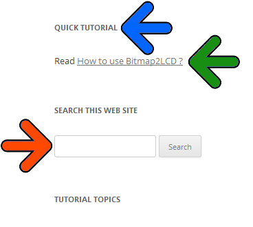
and you can browse the listed topics
Translation of these Tutorials
Translations Traductions Übersetzungen Traducciones_ Traduzione
Find Help and Tutorial using the Internal Web Browser
Use the Topic Menu Item as shown below
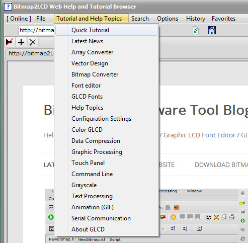
Fig 1 )
Already have discovered the presentation slide show on the website ?
It’s the same sideshow as the one included in the demo/trial version of the software tool. A general info about what this is it all about.
The Windows
The red frame below shows where, in the Main+Windows tab of the Main Menu, to open and show the different Windows of the Program
fig 2 )
Bitmap2LCD is a multi-window application and supports dual screen.
List of the windows : Main window, LCD Viewer, Configuration Settings, File explorer, Graphic and Editors Window, Tool menu, Work Canvas, Adjustments, Font Panel and internal Web Browser.
You can show or hide (minimize) the windows, move them to the secondary monitor.
.
.
Getting Started > Basic Settings
GETTING STARTED > BASIC SETTINGS
.
.
The Work Canvas
It’s the GRAPHIC EDITOR, the paintbox , You can draw pixels and shapes, import graphics into it. It has a user defined “color depth” which is the same as the target GLCD of the project.
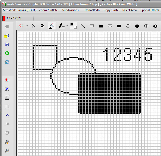
Fig 3 )
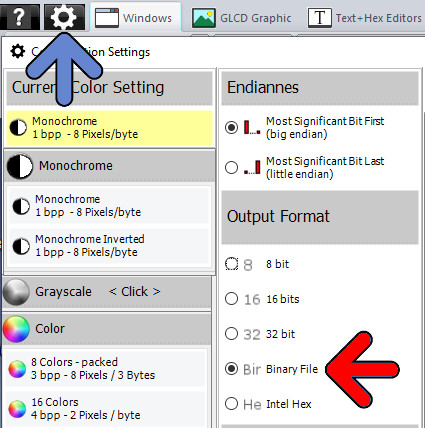
The Color Depth of the Work Canvas
Monochrome , Grayscale or Colors
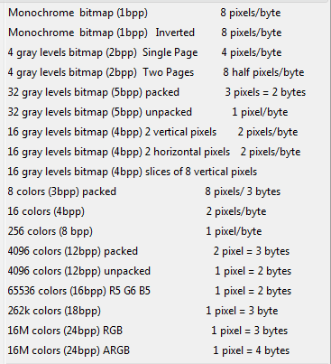
Fig 4 )
Load a graphic
LOADING A GRAPHIC USING A STANDARD WINDOWS DIALOG OR LOADING IT FIRST INTO PREVIEW ?
- You can either use the Load Graphic Dialog ( red frame )
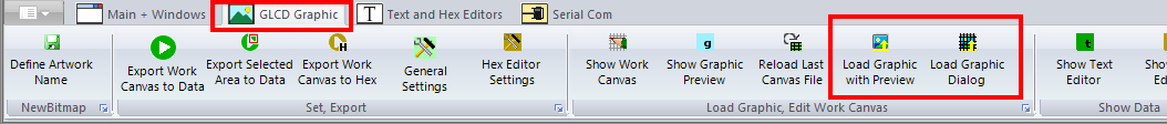
Fig 5 )
OR
- open / switch to the FILE EXPLORER
- In the list of files, click to select your particular graphic file you want to load (fig6 blue arrow) , it appears in the GRAPHICS PREVIEW window at the right side.
- Resize or turn/tilt the preview image using the buttons located at the top of the GRAPHIC PREVIEW.
- Double click in the graphics viewer (yellow arrow) or the click the import button located at the top or bottom of the preview (fig6. Green arrow)
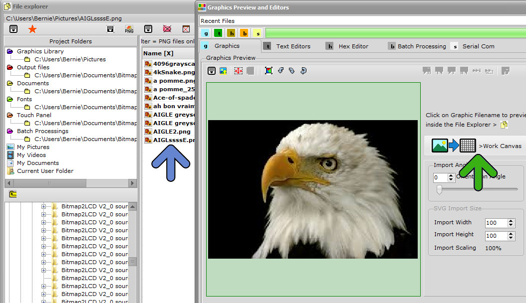
fig 6). File explorer view
If the graphic is larger than the WORK CANVAS a message box will ask you if you want resize the image to fit the canvas or not.
The Floating Selection Layer
MOVING THE GRAPHIC IMPORTED INSIDE THE FLOATING SELECTION LAYER ?
The graphic will be imported in the FLOATING SELECTION LAYER , not directly into the WORK CANVAS (fig7. imagine your own graphic inside the canvas)
The red frame (fig7. red arrow) around the canvas means that you will have to PASTE ![]() the graphic into the canvas after MOVING it, convert it. When outline frame is red, it means that a “floating ” SELECTION LAYER above the canvas is displayed…
the graphic into the canvas after MOVING it, convert it. When outline frame is red, it means that a “floating ” SELECTION LAYER above the canvas is displayed…
The imported graphic can be moved around above the Work canvas : Move/drag the red frame to the desired canvas location with the left mouse button pressed. (fig7. blue arrows)
Then PASTE ![]() the FLOATING SELECTION LAYER (fig7. green arrow) The red frame in the frame and around the work canvas disappears. (There are also other ways to Paste, in menus, using the return key etc..)
the FLOATING SELECTION LAYER (fig7. green arrow) The red frame in the frame and around the work canvas disappears. (There are also other ways to Paste, in menus, using the return key etc..)
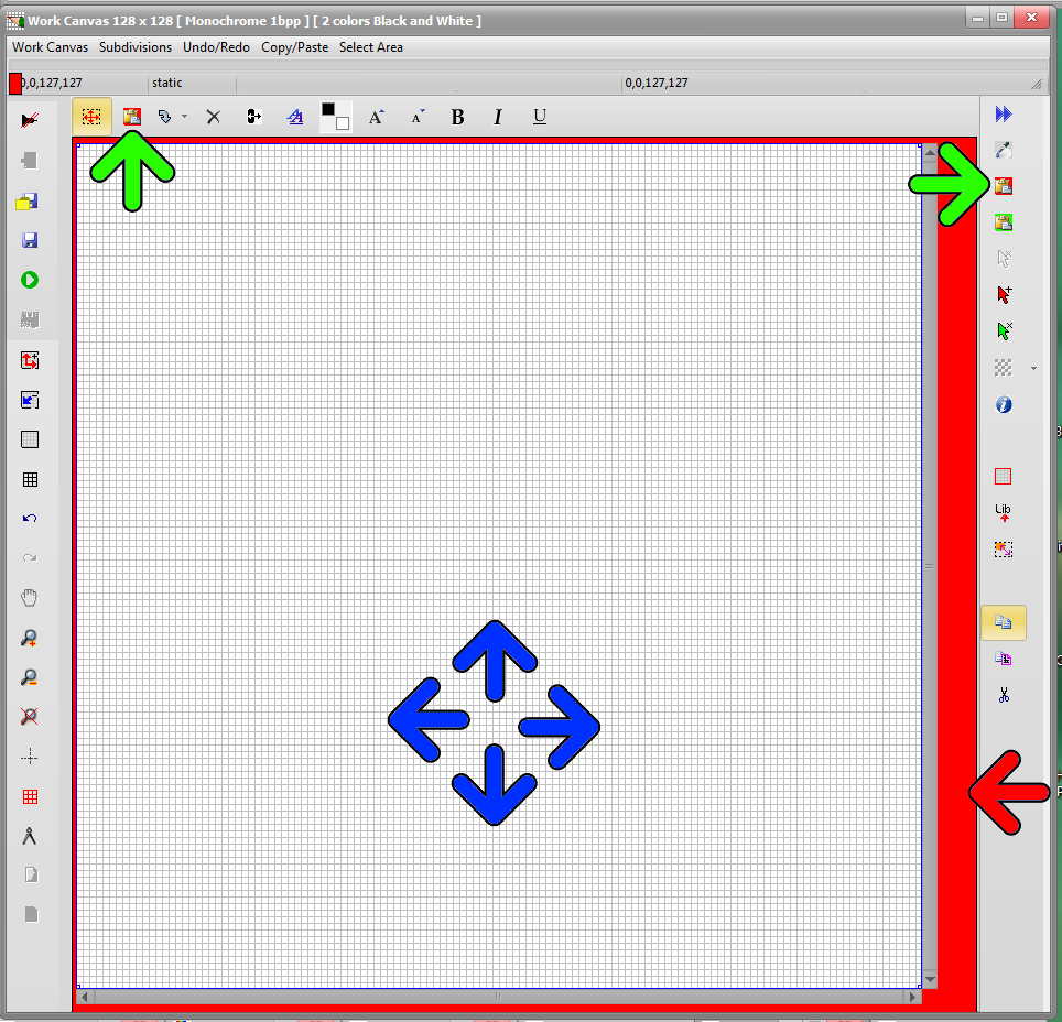
fig 7 ) Import a graphic file
.
Converting a bitmap to Monochrome
THRESHOLD LEVEL OR DITHERING ?
If you’re loading a COLOR graphic file to convert to black and white for MONOCHROME GLCDs you have the choice of applying a Black and White THRESHOLD level (red arrow), or applying a DITHERING (green arrow) with monochrome color reduction.
Dithering Parameters are located in the main menu of this Window
When the conversion to Black and white is finished, PASTE the floating SELECTION LAYER (Blue Arrow) to the WORK CANVAS
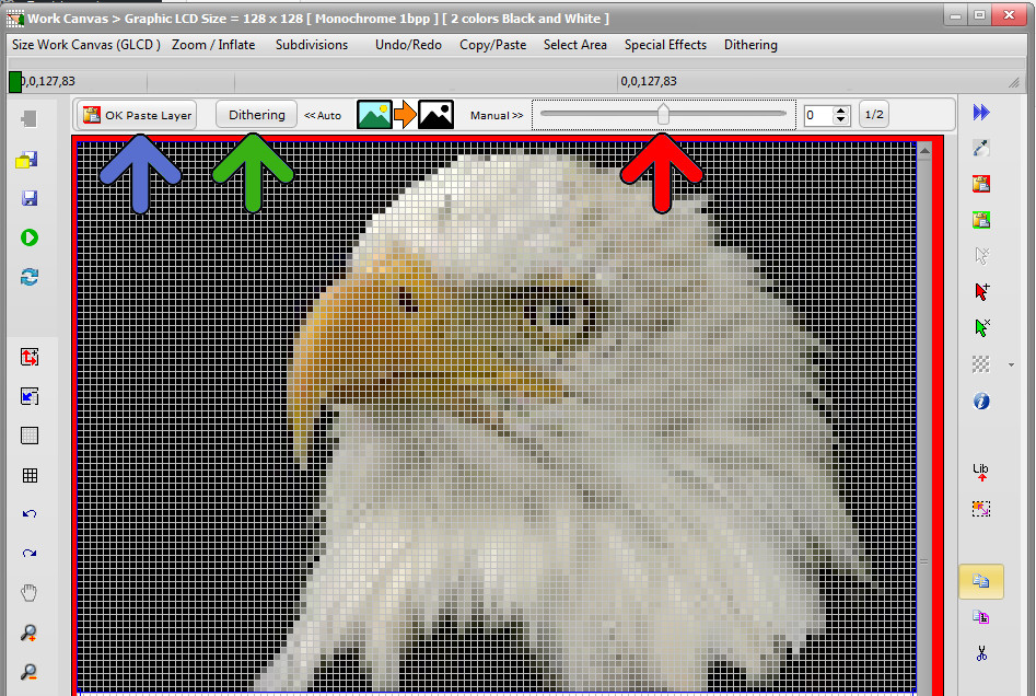
Fig 8 )
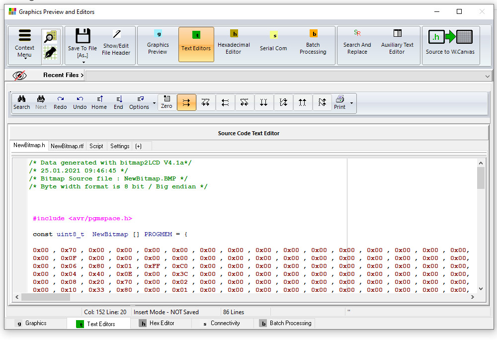
Converting a bitmap to GLCD data.
 Export WORK CANVAS Graphic To a DATA ARRAY inside the Text Editor
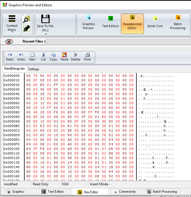
 Export WORK CANVAS graphic to Data inside the HEX Editor / BINARY file
 Export a selected area of the WORK CANVAS To a Data Array inside the TEXT EDITOR
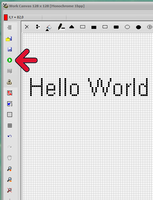
Fig 9 )
Start a Graphic To Data conversion (fig 9. red arrow)
Your hexadecimal file appears in the Text editor, formatted according to the defined configuration settings. (fig 10)
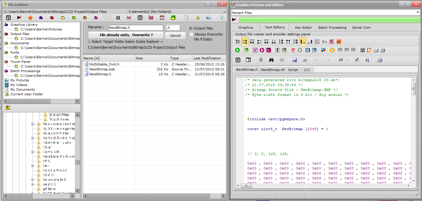
Fig 10) Bitmap has been converted to the Hexadecimal, decimal or binary file in the text editor.
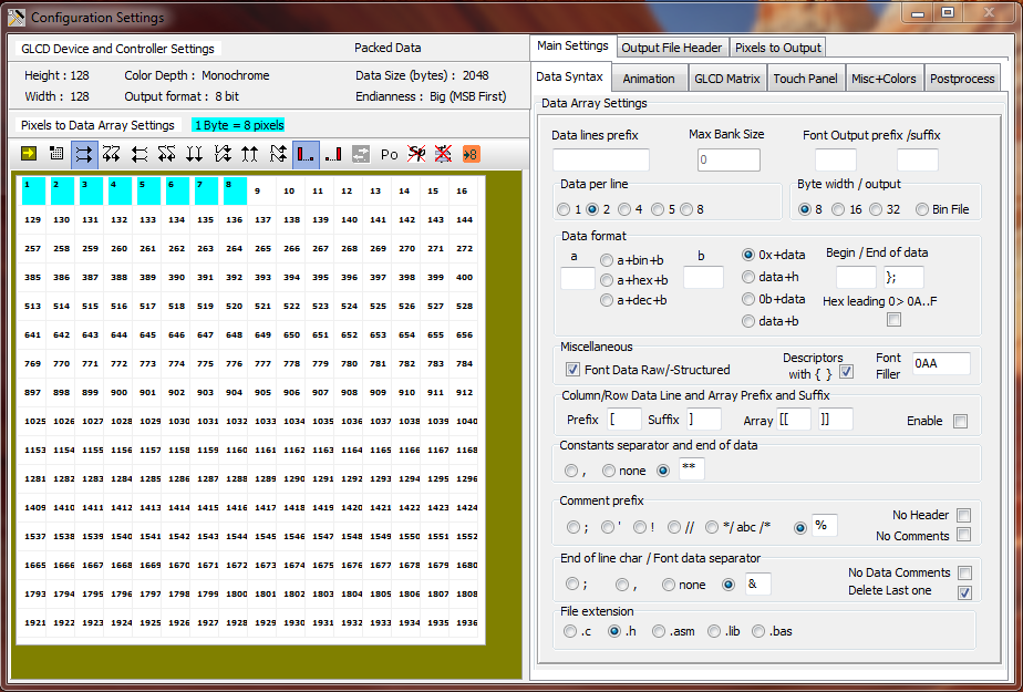
Basic Configuration
Where to find and change the SETTINGS
Example Of How to Convert A graphic To a Data Array
Example of how to convert a Graphic to a Array of Data
.
System font, Editable Font, Anti-aliased Font, GLCD Font with Bitmap2LCD
Info about Fonts in Bitmap2LCD
.
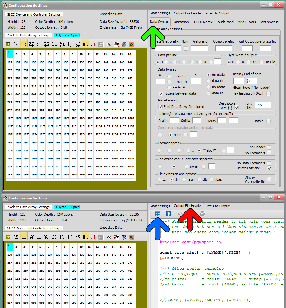
Projects, Artworks and Filenames
A PROJECT is a set of configuration settings ( There are many possible settings ! )
If you work on different GLCD projects, you can save the “current” settings inside a Project name. It’s the easiest and fastest way to switch from one to another.
A so called “Artwork” is a set of files related to the graphic source filename : In the below example a graphic saved for example as NewBitmap.BMP , will be converted to an output file called NewBitmap.h , and the associated touch panel file will then be named NewBitmap.TSC (Red Arrow)
When you save your Artwork with”Define Artwork Name” in the GLCD Graphic Tab (Red Frames), as a bitmap, you will change the basic filenames
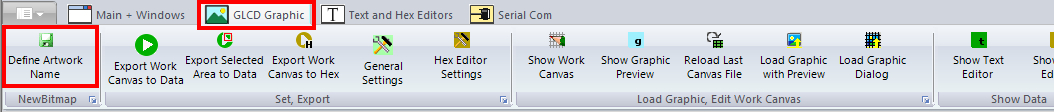
Fig 11 )
–
Color picker
Bitmap2LCD has built in functions which are very similar to the popular MS Paint program
You can select the foreground (PEN COLOR) and background colors (BRUSH COLOR) for painting and WRITING text by clicking in the color boxes of the menu window.
You can copy foreground color to background colors or swap them when clicking in the small boxes around the colors boxes.
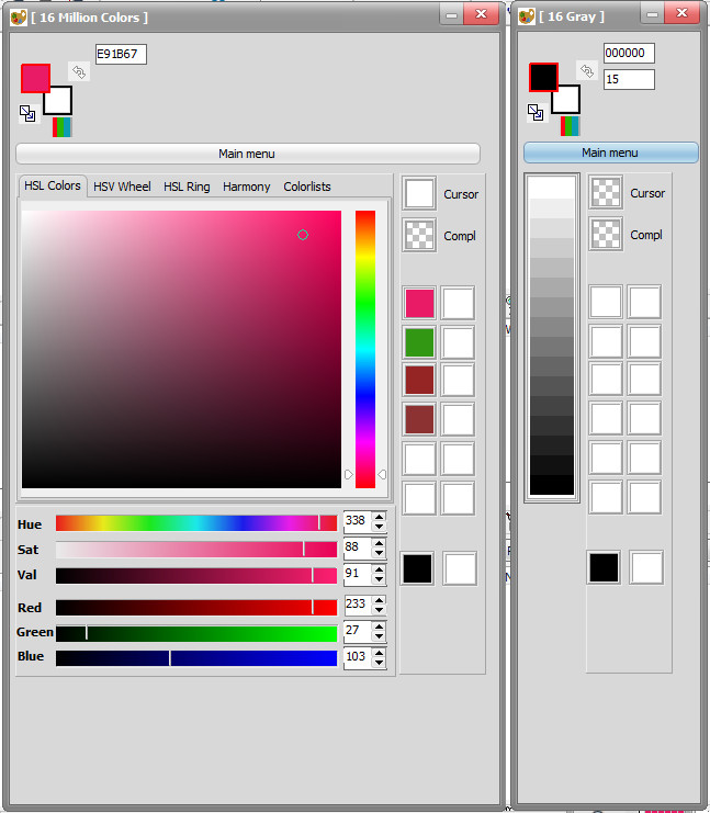 Fig 12 ) The Color Picker ( Here the Color mode Picker and the 16 gray shades mode picker )
Drawing tools
Buttons are located At the top of the Work Canvas
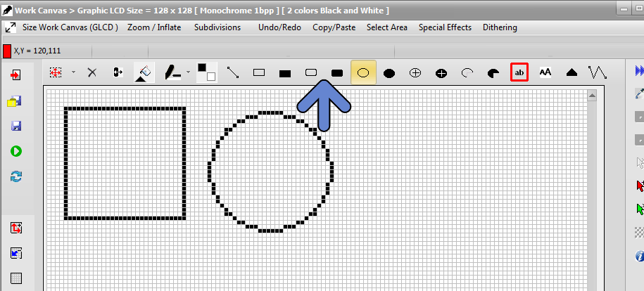 Fig 13) drawing tools
Write a text
Button is located at the top of the Work Canvas (blue arrow)
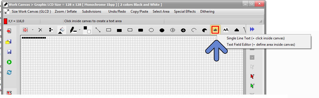
Fig 14 )
There are 2 different ways to write text inside the work canvas :
- The Text Field Editor
- The single Line Text editor
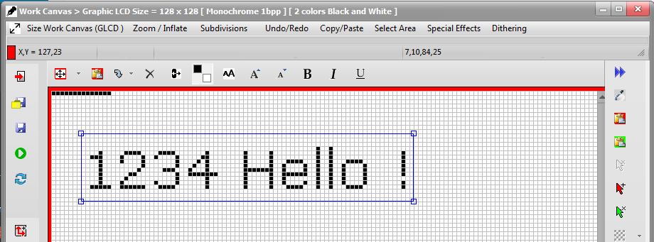
Fig 15 )
Example of using the single Line Text Editor, text can be moved and pasted with ![]()
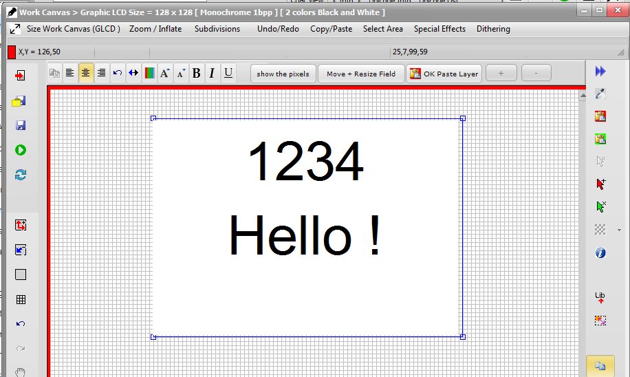
Fig 16 )
Example of using the Text Field Editor, text can be moved and pasted with ![]()
Working in Vector Mode (GLCD Library)
Using GLCD library functions like GLCD.rect(x,y,h,w) or GLCD.GotoXY(x,y) and similar :
Please follow this link :
Target Code Example : Displaying a bitmap on an
Atmel AVR MCU
.
Software Updates
With Standard Edition of Bitmap2LCD, you get unlimited Software Updates
Details About Software Updates
Bitmap2LCD development and Support
A feature you would like to see implemented not yet available ?
submit us your Idea ! Need support ? Contact us !