News : Bitmap2LCD Version V4.9b 
Run Bitmap2LCD on computer with dual screen or large device !
Bitmap2LCD has a number of “flying” windows. The Work Canvas, can be very large, as every single GLCD pixel is zoomed.
>.<
Run Bitmap2LCD on computer with dual screen or large device !
Bitmap2LCD has a number of “flying” windows. The Work Canvas, can be very large, as every single GLCD pixel is zoomed.
>.<
Bitmap2LCD is a tool for programming small Graphic LCDs in embedded systems and a programmable graphic and text processing tool.
Standard + Extended Edition
( V4.9b )
Load a text file of a list of International Characters as a List of Hex Addresses or Address Ranges and export to Data in a single run.
Example of a mixed list of Unicode char addresses and ranges of addresses
0x0020-0x002F
0x0A96
0x0070-0x007F
0x0180-0x018f
0x03A8
Input Format : A single Unicode Char Address per line
Example : 0x0150 ( Or $0150 )
Input Format : A range of Unicode Chars Addresses per line
Example : 0x0150-0x155 ( with ‘-‘ as separator )
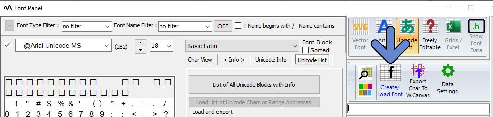
2. Menu Unicode List / Load List of Unicode Chars button
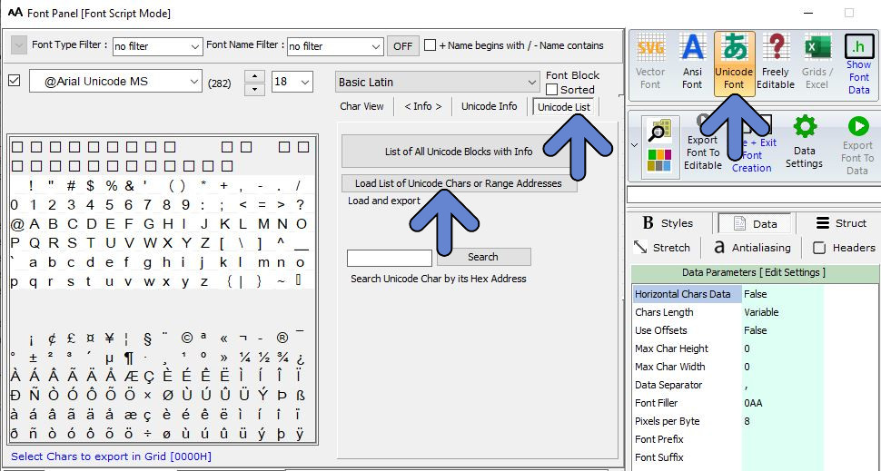
3. Load the text file and export the data
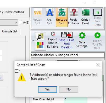
4. Processing export to data…
Bitmap2LCD is a tool for programming small Graphic LCDs in embedded systems and a programmable graphic and text processing tool.
Update V4.7b
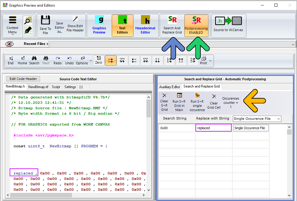
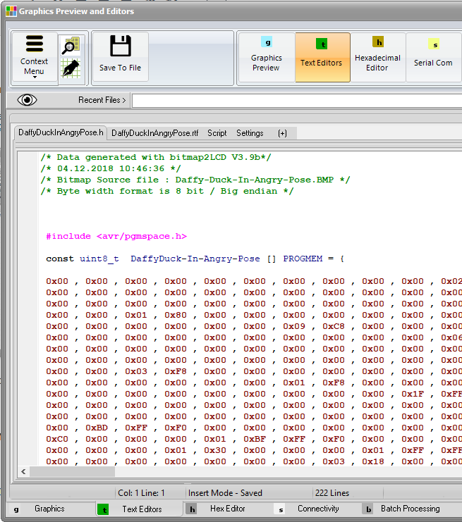
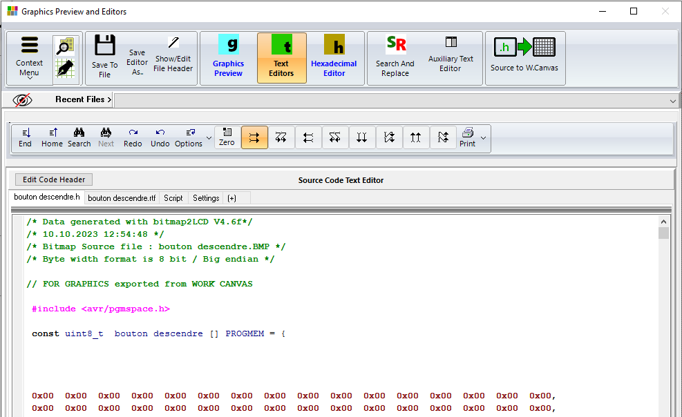
There’s a Search and Replace Grid in the Graphics Preview and Editors window.
1. Show the S+R Grid (blue arrow). (Same button to hide the Grid)
2.Define Search String, Replace String, if needed, one of the functions of the box.
3. Click on Run S+R in Main button to perform the data processing in the source code Text Editor. The occurrences counter will show the number of changes (orange arrow).
In this example “0x00” has been replaced by “replaced”, one time only in the whole source code. (purple frames) If a Function Cell is void in the Grid, the S+R task applies for the whole source code.
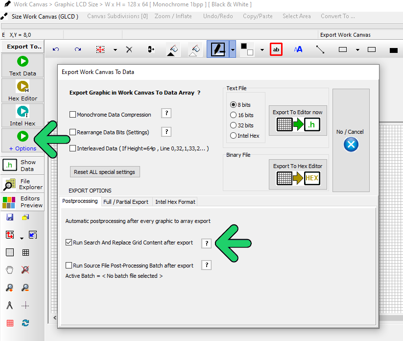
Automatic Postprocessing
The tasks defined in the S+R grid can automatically be executed after an export of GLCD data by switching the postprocessing to ENABLE.(green arrow) in the main menu or in the Export Canvas to Data with Options window (green arrows below)
Auxiliary Editor
A tab opens an Auxiliary Editor to ease comparing original and postprocessed source codes.
>.<
Presentation of Bitmap2LCD (Youtube)
Bitmap2LCD is a software tool for programming small Graphic LCDs in embedded systems and a programmable text and graphic processing tool.
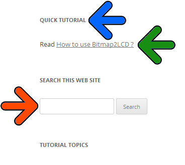
At the TOP RIGHT HAND SIDE of this BLOG you’ll find
1. For example the link (green arrow) of this Quick Tutorial
2. Search this website using keywords (orange arrow)
Filter with the list of topics / categories
Translations Traductions Übersetzungen Traducciones_ Traduzione
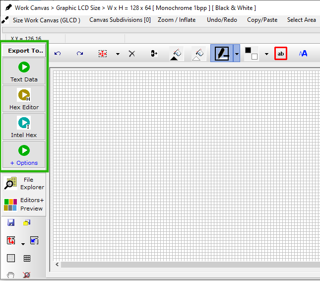
In the red frame below (Windows tab – Main Menu ) the windows of the Program
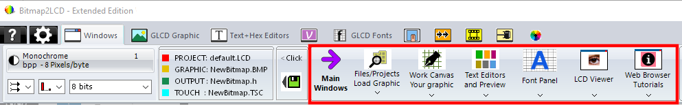
Bitmap2LCD is a floating multi-window application for dual screen computers.
It’s the GRAPHIC EDITOR, the Paintbox : Import graphics into it, draw pixels and shapes, add text…
It has a user defined size and color depth matching with the target Graphic LCD device of the project.
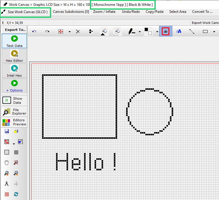
Monochrome , Grayscale or Colors
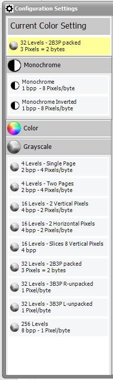
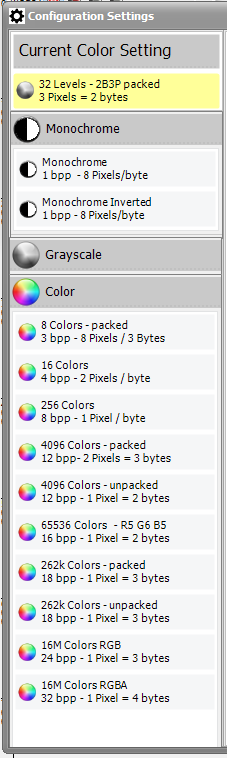
Fig 4a+b )
Variant 1 : Dialog (red frame)
Variant 2: File explorer
If graphic is larger than WORK CANVAS, a dialog shows to resize to fit the Work Canvas or not.
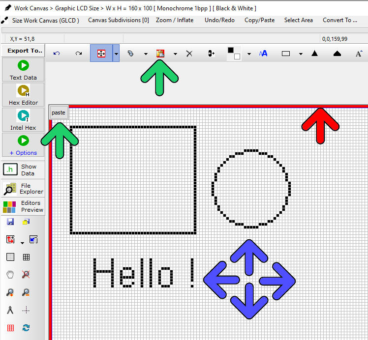
MOVING THE IMPORTED GRAPHIC INSIDE THE FLOATING SELECTION LAYER
An import of a graphic takes place on the FLOATING SELECTION LAYER, A red frame (red arrow) around the canvas shows an active selection layer.
After MOVING the selection layer (blue arrows), PASTE ![]() the graphic (green arrows) to the Work Canvas.
the graphic (green arrows) to the Work Canvas.
.
2 variants color to monochrome conversion : THRESHOLD LEVEL and DITHERING
Variant 1.THRESHOLD level (red arrow) : move the cursor .
Variant 2. DITHERING (green arrow) with monochrome color reduction. (Dithering Parameters are located in the main menu convert to.. )
After conversion, PASTE the floating SELECTION LAYER (Blue Arrow) to CANVAS
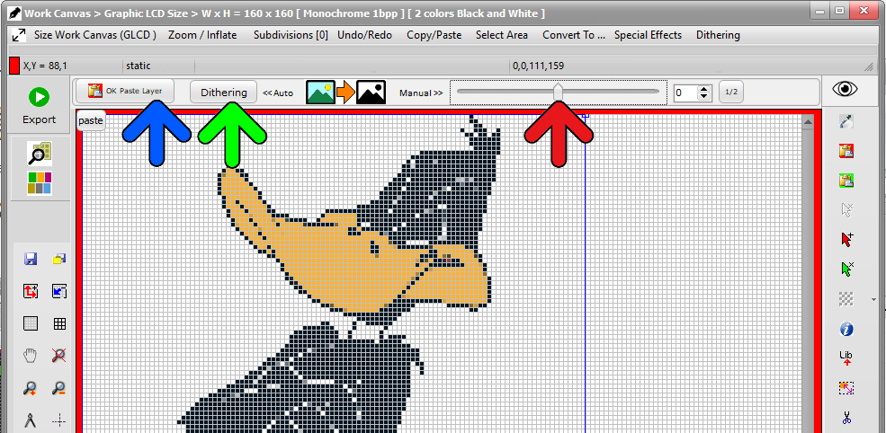
Fig 8 )
There are several options to choose from :
Your hexadecimal file is in the Text editor in the format defined in the configuration settings.
Example of how to convert a Graphic to a Array of Data
.
Info about Fonts in Bitmap2LCD
.
A PROJECT is a set of configuration settings
For different GLCD projects, the specific set of settings can be saved as a Project. It allows to switch from one to another.
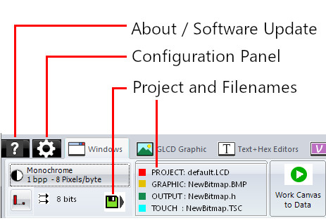
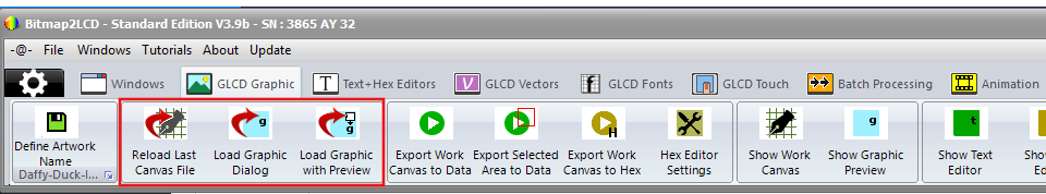
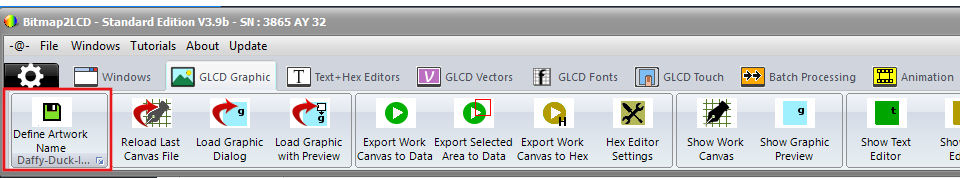
A so called “Artwork” is a set of files related to the graphic source filename : In the below example a graphic saved for example as NewBitmap.BMP , will be converted to an output file called NewBitmap.h , and the associated touch panel file will then be named NewBitmap.TSC (red arrow)
When you save your Artwork with”Define Artwork Name” in the GLCD Graphic Tab (red frames), as a bitmap, you will change the basic filenames.
–
The Color Picker depends of the selected Color Depth of the Work Canvas
The picker is located in the right panel of the Work Canvas window (purple arrows).
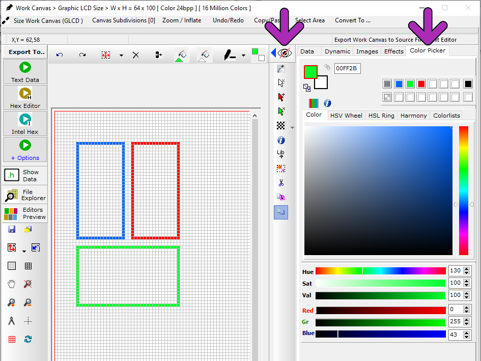
Define foreground Color (PEN COLOR) and background color (BRUSH COLOR) for painting and Writing text in the Work Canvas
Copy foreground color to background color, swap the colors etc…
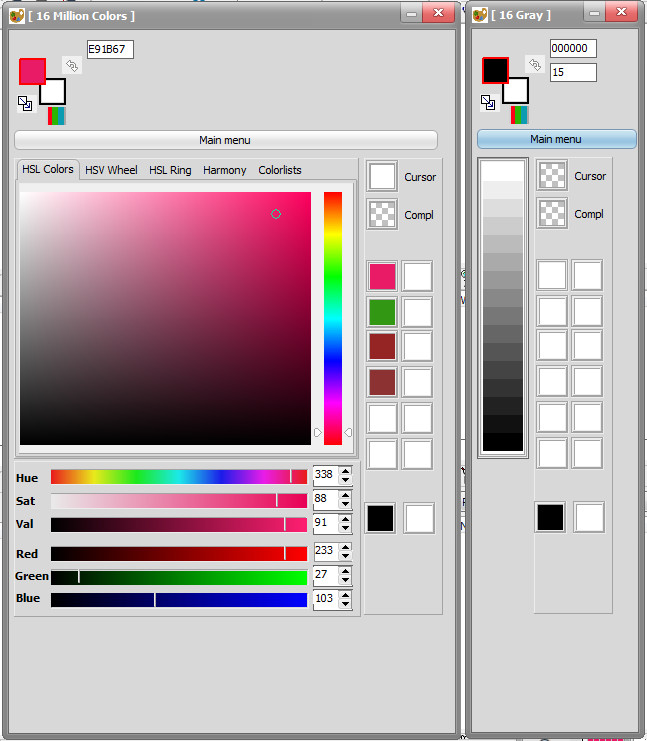
Example of color pickers, (Color mode and 16 gray shades)
Write Text Button located at the top of the Work Canvas (blue arrow)
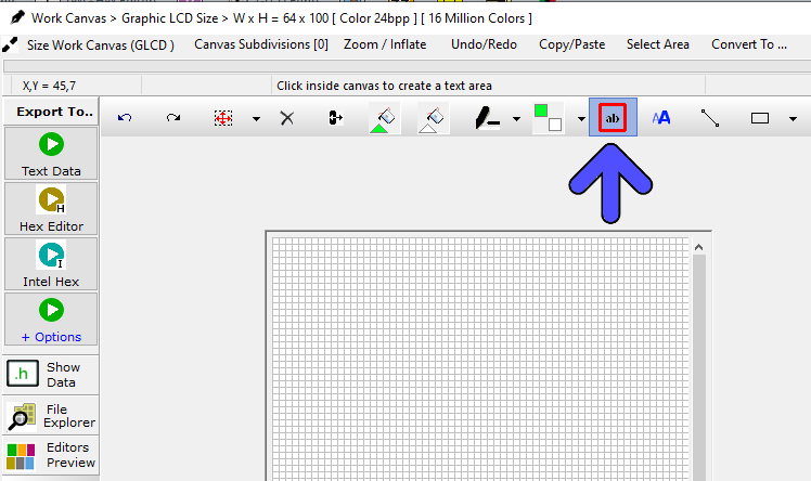
2 variants available for writing text :
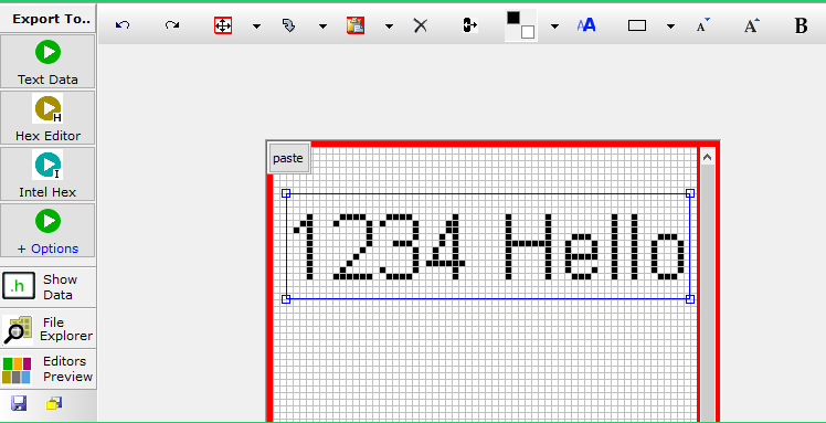
The single Line Text Editor, text can be moved and then pasted to canvas ![]()
For GLCD library functions like GLCD.rect(x,y,h,w) or GLCD.GotoXY(x,y) or similar…
.
Lifelong software Updates for Standard and Extended Edition :
Details About Software Updates
A feature not implemented or not yet available ?
submit us your Idea ! Need support ? Contact us !
Bitmap2LCD is a tool for programming small Graphic LCDs in embedded systems and a programmable graphic and text processing tool.
Update V4.6c
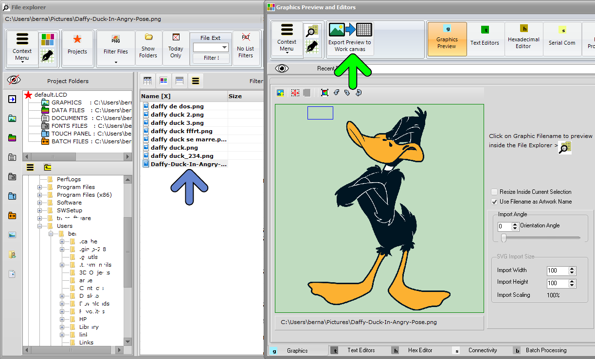
1. Open the File Explorer Window
2. If needed, select the Graphics Project Folder
3. Select the Graphic Filename
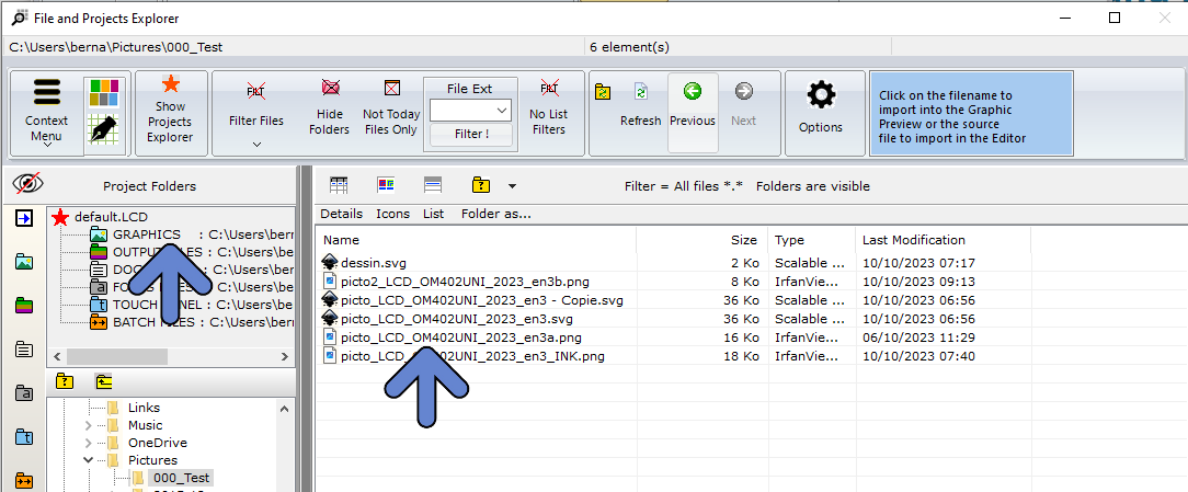
4. Graphic is opened in the Graphics Preview Window
5. If needed, adjust options like size, color reduction and orientation.
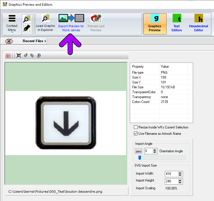
6. Export Preview to the Work Canvas( purple arrow )
7. Graphic is inside the FLOATING SELECTION LAYER, above the Work Canvas surrounded by a red frame
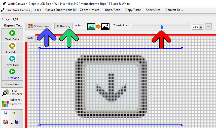
8. In this example, a conversion to monochrome is required. (monochrome GLCD)
9. Either choose Black and White THRESHOLD LEVEL with Adjustment Slider conversion or one of the DITHERING ALGORITHMS, like for example Floyd Steinberg.
10. If needed, drag the FLOATING SELECTION LAYER to its destination position on the canvas.
11. PASTE the selection layer to the WORK CANVAS ( blue arrow )
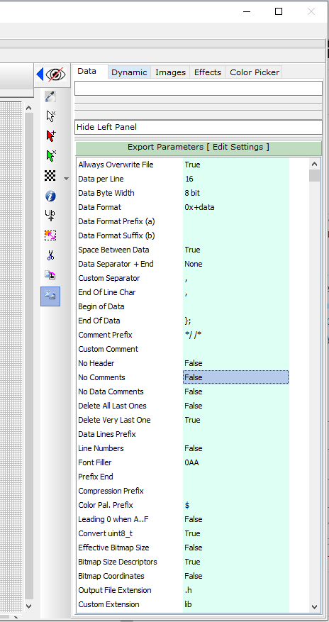
12. If needed, adjust the export parameters in the green column, Data Tab
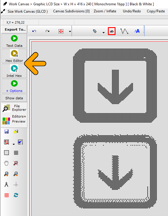
12. Export the Work Canvas to data array (Choose one of the Export Options : orange arrow)
13. Job done !
Note : With the 8 buttons with arrows at the top of the source code editor, adjust the data direction to match the display memory of the GLCD controller.
…
About : Font panel and font generator data structures
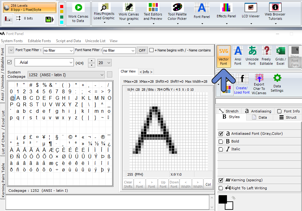
Font Panel ( SVG / ANSI / UNICODE and Editable Fonts )
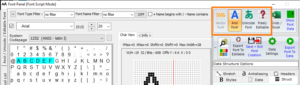
4 different font categories are available : ANSI and Unicode international System fonts (installed on Windows) , the SVG fonts (for grayscale 256) based on vector graphics for a better anti-aliasing quality, and Freely Editable Font, for customized bitmap glyphs.
^
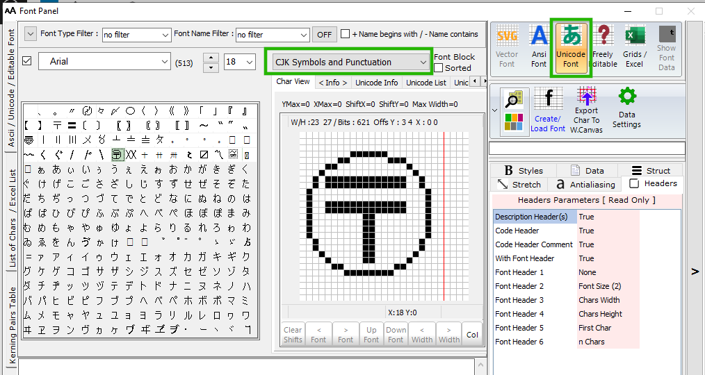
Unicode block selection (green frame)
Font Panel ( EDITABLE Font )
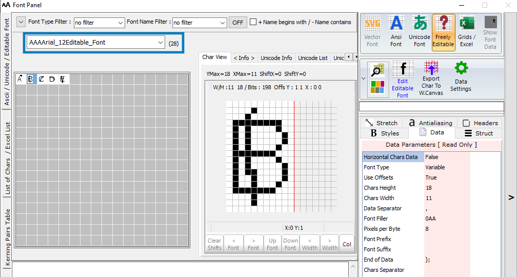
An Editable Font can be an import of a system font + edits or created from scratch.
In this example only 5 chars
List of the existing Editable Fonts (blue frame)
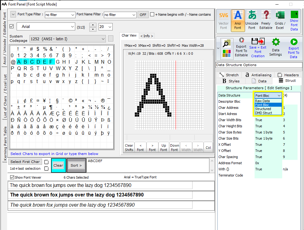
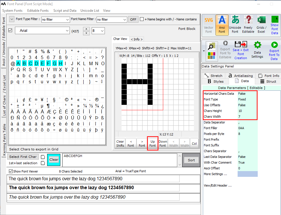
Font Panel ( ANSI Font )
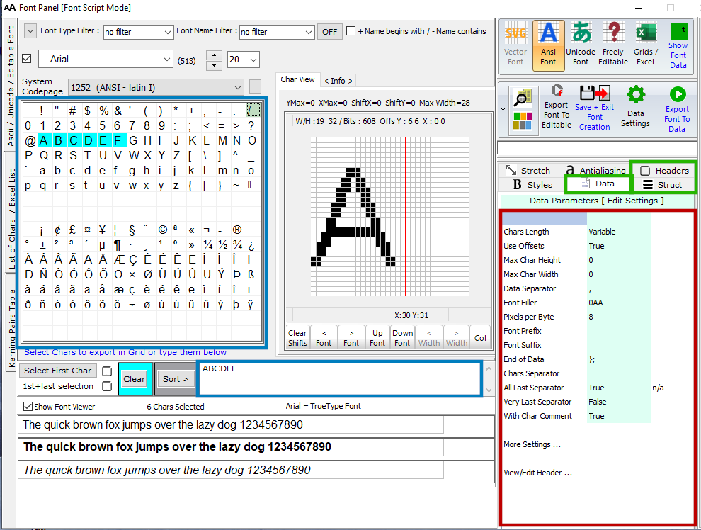
Font Settings in 3 panels : Structure, Header, and Data (green frames)
The parameters can be edited (when green background) in these 3 fields (red frame)
The chars selected in the Grid (blue frame) will be exported to data
Font panel > Structure Parameters
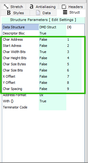
The Parameters in the green frame are separated for each Data Structure (1st Parameter of this list) These data are then present or not in the Descriptor blocs of the output data.
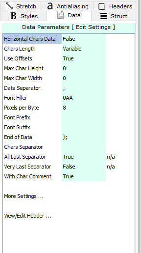
Font panel > Data Parameters
Font panel > Headers Parameters
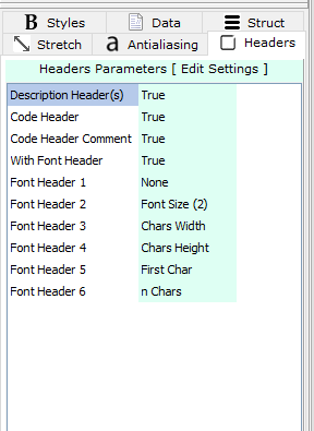
The font headers such as the description and the font header code exported at the top of the data output.
Font panel > Font Data Structure
>.<
Data Structures :
Raw Data, Font Bloc, Structured and DMD struct are different outputs layouts for fonts.
The differences in headers, bitmap glyphs and descriptors
Example for “RAW Data” structure
Optional descriptors at the end
/* >>> Code Header */
/* ( Bitmap Glyphs ) */
/* @ 0 Char:’A’ Width in bits :10 */
0x08 , 0x00 , /* ____#___________ */
0x14 , 0x00 , /* ___#_#__________ */
0x14 , 0x00 , /* ___#_#__________ */
0x14 , 0x00 , /* ___#_#__________ */
0x22 , 0x00 , /* __#___#_________ */
0x22 , 0x00 , /* __#___#_________ */
0x7F , 0x00 , /* _#######________ */
0x41 , 0x00 , /* _#_____#________ */
0x80 , 0x80 , /* #_______#_______ */
0x80 , 0x80 , /* #_______#_______ */
/* @ 20 Char:’B’ Width in bits :10 */
0x7E , 0x00 , /* _######_________ */
0x41 , 0x00 , /* _#_____#________ */
0x41 , 0x00 , /* _#_____#________ */
0x41 , 0x00 , /* _#_____#________ */
0x7E , 0x00 , /* _######_________ */
0x41 , 0x00 , /* _#_____#________ */
0x41 , 0x00 , /* _#_____#________ */
0x41 , 0x00 , /* _#_____#________ */
0x41 , 0x00 , /* _#_____#________ */
0x7E , 0x00 /* _######_________ */
};
const uint8_t Arial_10_1252_(ANSI_-_latin_I)_Descriptors[][] PROGMEM = {
{0x41,0,10,10,100,160,0,30}, /* ‘A’ */
{0x42,20,10,10,100,160,0,30} /* ‘B’ */
>.<
Example for “Font BLOC” data structure
Optional Font Header at the top
Optional descriptors at the top of every bitmap glyph
const unsigned char Arial_10_1252_(ANSI_-_latin_I)_Bitmaps[] = {)
0x00,0x3E,13,16,0x00,2, (font header)
/* ‘A’ */
0x41,0,10,10,100,160,0,30,
0x08 , 0x00 , /* ____#___________ */
0x14 , 0x00 , /* ___#_#__________ */
0x14 , 0x00 , /* ___#_#__________ */
0x14 , 0x00 , /* ___#_#__________ */
0x22 , 0x00 , /* __#___#_________ */
0x22 , 0x00 , /* __#___#_________ */
0x7F , 0x00 , /* _#######________ */
0x41 , 0x00 , /* _#_____#________ */
0x80 , 0x80 , /* #_______#_______ */
0x80 , 0x80 , /* #_______#_______ */
/* ‘B’ */
0x42,20,10,10,100,160,0,30,
0x7E , 0x00 , /* _######_________ */
0x41 , 0x00 , /* _#_____#________ */
0x41 , 0x00 , /* _#_____#________ */
0x41 , 0x00 , /* _#_____#________ */
0x7E , 0x00 , /* _######_________ */
0x41 , 0x00 , /* _#_____#________ */
0x41 , 0x00 , /* _#_____#________ */
0x41 , 0x00 , /* _#_____#________ */
0x41 , 0x00 , /* _#_____#________ */
0x7E , 0x00 /* _######_________ */
};
>.<
Example for *Structured” data structure
Bitmap glyphs in blocks, Descriptors in blocks at the end
/* >>> Code Header */
/* ( Bitmap Glyphs ) */
static const uint8_t image_data_Arial_10_1252_(ANSI_-_latin_I)_0x41[20] =
{
0x08 , 0x00 , /* ____#___________ */
0x14 , 0x00 , /* ___#_#__________ */
0x14 , 0x00 , /* ___#_#__________ */
0x14 , 0x00 , /* ___#_#__________ */
0x22 , 0x00 , /* __#___#_________ */
0x22 , 0x00 , /* __#___#_________ */
0x7F , 0x00 , /* _#######________ */
0x41 , 0x00 , /* _#_____#________ */
0x80 , 0x80 , /* #_______#_______ */
0x80 , 0x80 /* #_______#_______ */
};
static const uint8_t image_data_Arial_10_1252_(ANSI_-_latin_I)_0x42[26] =
{
0x7E , 0x00 , /* _######_________ */
0x41 , 0x00 , /* _#_____#________ */
0x41 , 0x00 , /* _#_____#________ */
0x41 , 0x00 , /* _#_____#________ */
0x7E , 0x00 , /* _######_________ */
0x41 , 0x00 , /* _#_____#________ */
0x41 , 0x00 , /* _#_____#________ */
0x41 , 0x00 , /* _#_____#________ */
0x41 , 0x00 , /* _#_____#________ */
0x7E , 0x00 /* _######_________ */
};
/* >>> Optional Char Descriptors */
/* ( Char Adress Start adress Width in bits Height in bits Char Bytes Size in bits X Offset Y Offset Char Spacing bits ) */
static const tImage Arial_10_1252_(ANSI_-_latin_I)_array_[] = {
// character : ‘A’
{0x41,0,10,10,100,160,0,30 , &Arial_10_1252_(ANSI_-_latin_I)_0x41},
// character : ‘B’
{0x42,20,10,10,100,160,0,30 , &Arial_10_1252_(ANSI_-_latin_I)_0x42}
};
const tfont Arial_10_1252_(ANSI_-_latin_I) = { 2 , Arial_10_1252_(ANSI_-_latin_I)_array };
>.<
Example for “DMD Struct” data structure
Optional Font Header at the top
Descriptors in blocks at the top (Here widths only )
static const uint8_t Arial_10_1252_(ANSI_-_latin_I)_Bitmaps[2][] PROGMEM = {
0x00,0x30,13,16,0x00,2, (font header)
/* >>> Code Header */
/* ( Width in bits ) */
10, /* ‘A’ */
10 /* ‘B’ */
,
/* ( Bitmap Glyphs ) */
/* @ 0 Char:’A’ Width in bits :10 */
0x08 , 0x00 , /* ____#___________ */
0x14 , 0x00 , /* ___#_#__________ */
0x14 , 0x00 , /* ___#_#__________ */
0x14 , 0x00 , /* ___#_#__________ */
0x22 , 0x00 , /* __#___#_________ */
0x22 , 0x00 , /* __#___#_________ */
0x7F , 0x00 , /* _#######________ */
0x41 , 0x00 , /* _#_____#________ */
0x80 , 0x80 , /* #_______#_______ */
0x80 , 0x80 , /* #_______#_______ */
/* @ 20 Char:’B’ Width in bits :10 */
0x7E , 0x00 , /* _######_________ */
0x41 , 0x00 , /* _#_____#________ */
0x41 , 0x00 , /* _#_____#________ */
0x41 , 0x00 , /* _#_____#________ */
0x7E , 0x00 , /* _######_________ */
0x41 , 0x00 , /* _#_____#________ */
0x41 , 0x00 , /* _#_____#________ */
0x41 , 0x00 , /* _#_____#________ */
0x41 , 0x00 , /* _#_____#________ */
0x7E , 0x00 /* _######_________ */
};
Bitmap2LCD is a programming tool for small Graphic LCDs in embedded systems.
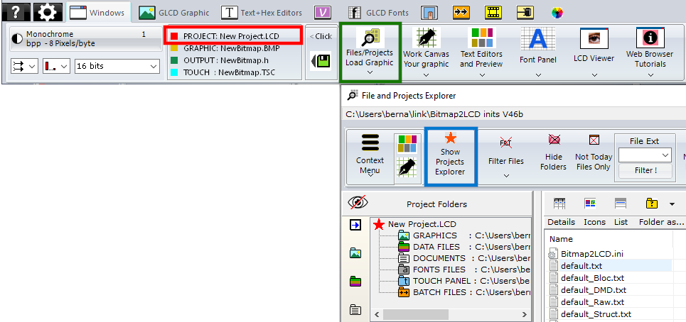
The current active project is displayed in the Windows Tab of the Main Menu (red frame) By clicking in this area, you have direct access to the Project Manager. There’s originally only 1 project called default.LCD
You can add other projects to the system. Every project is a separate set of settings, project folders, work canvas sizes etc.. To access the Project Manager, click on the Files/Projects Button (green frame) then Show Projects Explorer on the File explorer Window (blue frame)
The File explorer Window
The field at the top left side of the file explorer is the “Project Folders Management” and “the Project Management”.
With the buttons showing colored folder icons at the right side of the below blue arrow, you can define the folders where you want to convert, find and save the files of the current project.
By clicking on one of these colored folder icons, you define the currently active folder in the tree as the project folder for Graphics, Output files, Project Documents, Fonts or Touch Screen files.
When clicking on the links inside the field, you have a quick access to the different project folders.
When for example clicking on “Graphics Library“, you switch the File List Filter to “all graphic files” excluding the other files type from the list. (This behavior can be enabled or disabled in the Filter pop-up menu)
These project folders and all the configuration settings (GLCD size, Data Direction, File Header etc..) are saved to the disk as a set of project settings.
By clicking on the Show Projects Explorer button (orange star icon) in the menu bar (blue arrow) you can switch the view to the project management.
The Project Manager
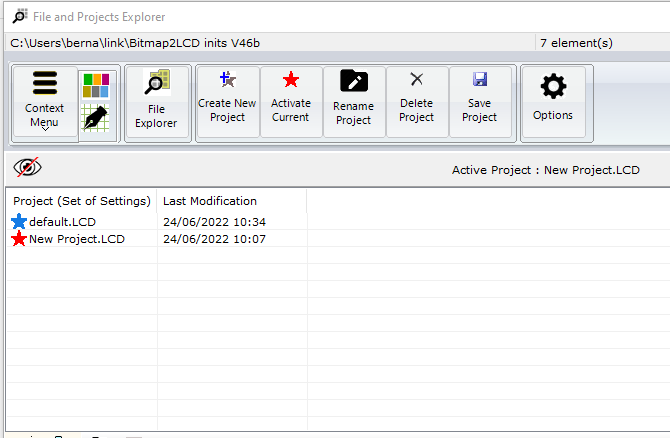
The Project list shows the list of available projects. The list can be void in the case only the default project exists. Otherwise, like in this example, the list shows and the active project is marked with a red arrow. The other projects are marked with blue arrows.
The files attached to a project are are located in the documents/bitmap2LCD inits (version) folder.
With the Buttons in the Menu Bar at the top of the project list, you can Create, Activate, Rename and delete Projects.
>.<
Import Projects from previous versions
Copy the project files attached to a previous Project from the documents/bitmap2LCD inits (previous version) folder to the documents/bitmap2LCD inits (current version) folder.
>.<
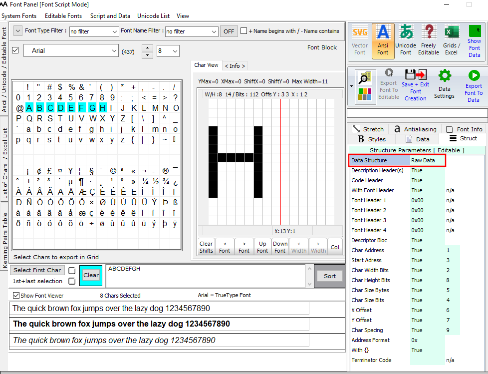
From Update V4.5
For small monochrome font chars, a single line per char data output has been implemented :
Basic conditions :
2. Then select some chars in the chars grid or type them inside the list of chars ( selected chars are displayed in light blue A…H )
>.<
The script components [&***] can be included only once and will be replaced by the data or value when the data array is generated. Not needed script components can be deleted.
[&NAME]
The [$NAME] and the image size and position are optional and can be placed optionally anywhere in the header.
[&SIZE]
Same for Size of Data
[&TRUEORG]
This is the script component if present in the file, to indicate that you want to have the XPOS and YPOS origins of a reduced dynamic table of constants ( a part of the display you want to change ) given from the X0,Y0 corner you selected in the table translation manager window.
[&XPOS]
[&YPOS]
[&WIDTH]
[&HEIGHT]
The corner position on the Work Canvas and the size of the converted graphic area can be exported into the file.
There are more script components, for the font generation and the data compression. See the above default header script.
//** Example for for Images and Graphics Conversion!
#include <avr/pgmspace.h>
const uint8_t [&NAME][] PROGMEM = {
[&TRUEORG]
[&XPOS],
[&YPOS],
[&WIDTH],
[&HEIGHT],
//** These are the X and Y position
//** and the Width and Height of an
//** exported graphic (optional)
//** for graphics conversion with data compression
[&COMPRESSION]
const uint8_t [&CNAME][&CSIZE] PROGMEM = {
Header Include for Fonts
[&FONT INCLUDE]
/* // Structured Font Output Include
typedef struct {
long int code;
const tImage *image;
} tChar;
typedef struct {
int length;
const tChar *chars;
} tFont;
*/
[&/FONT INCLUDE]
[&FONT BITMAPS]
const uint8_t [&FNAME][&FNUMBEROFCHARS][&FBYTESPERCHAR] PROGMEM = {
[&FONT DESCRIPTORS]
const uint8_t [&DNAME][][2] PROGMEM = {
[&FONT END]
Update V4.3
To get GLCD fonts with better antialiasing rendering quality, in apps with grayscale TFT displays (256 gray shades) Bitmap2LCD can output Scalable Vector Graphics (SVG fonts)
>.<