Tag Archives: LCD software

Bitmap2LCD : Project Folders and Project Management

Bitmap2LCD is a programming tool for small Graphic LCDs in embedded systems.

Project Folders and Project Management

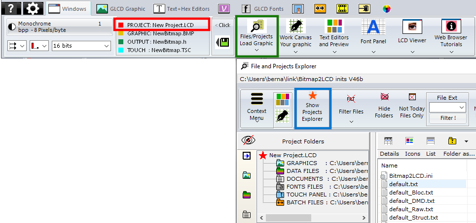
The current active project is displayed in the Windows Tab of the Main Menu (red frame) By clicking in this area, you have direct access to the Project Manager. There’s originally only 1 project called default.LCD

You can add other projects to the system. Every project is a separate set of settings, project folders, work canvas sizes etc.. To access the Project Manager, click on the Files/Projects Button (green frame) then Show Projects Explorer on the File explorer Window (blue frame)

The File explorer Window

The field at the top left side of the file explorer is the “Project Folders Management” and “the Project Management”.

With the buttons showing colored folder icons at the right side of the below blue arrow, you can define the folders where you want to convert, find and save the files of the current project.

By clicking on one of these colored folder icons, you define the currently active folder in the tree as the project folder for Graphics, Output files, Project Documents, Fonts or Touch Screen  files.

When clicking on the links inside the field, you have a quick access to the different project folders.

When for example clicking on “Graphics Library“, you switch the File List Filter to “all graphic files” excluding the other files type from the list. (This behavior can be enabled or disabled in the Filter pop-up menu)

These project folders and all the configuration settings (GLCD size, Data Direction, File Header etc..)  are saved to the disk as a set of project settings.

By clicking on the Show Projects Explorer button (orange star icon) in the menu bar (blue arrow) you can switch the view to the project management.

The Project Manager

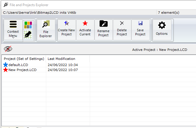
The Project list shows the list of available projects. The list can be void in the case only the default project exists. Otherwise, like in this example, the list shows and the active project is marked with a red arrow. The other projects are marked with blue arrows.

The files attached to a project are are located in the documents/bitmap2LCD inits (version) folder.

With the Buttons in the Menu Bar at the top of the project list, you can Create, Activate, Rename and delete Projects.

>.<

Import Projects from previous versions

Copy the project files attached to a previous Project from the documents/bitmap2LCD inits (previous version) folder to the documents/bitmap2LCD inits (current version) folder.

>.<

GLCD Data Output Settings in Bitmap2LCD

Bitmap2LCD is a tool for programming small Graphic LCDs in embedded systems.

This article is only for releases before V2.5

Let’s look how to configure the GLCD data output settings :

The generated data array file (orange arrow, in the picture below) can be configured to meet the syntax requests of your compiler or assembler. There are many possible settings, to make it possible to match the tool with most of the compilers of the market.

At first, you define the table data settings (red arrow)

  • Data Width format. ( 8,16 or 32 bits data)
  • Binary, Hex or decimal format.
  • Syntax of Data Byte/Word (make it compatible with your favorite compiler, assembler)
  • Type of file (extension)

As next, you define the header syntax (green arrow)

  • Click on the button and the header script is loaded into the editor. Modify it to meet your requirements.
  • When ready, quit the header editor by clicking the same button (green arrow at the right) or the quit button. (script is auto-saved)
  • Find more about the header syntax at the end of this article.


As next, you define the way the data arrays are arranged to correctly fit in the DDRAM of your LCD controller. These settings must be compatible with the LCD display functions in the GLCD Library you use in your project (blue arrow)

  • The origin corner X0,Y0
  • Data direction (The direction in which the pixels slices are taken from the work canvas and converted to GLCD data, for example in slices or in full canvas height or full canvas width. A slice is 8 pixels in monochrome mode and 2 pixels in 4bpp grayscale mode)
  • The Endianness (Most Significant Bit is first or last)
  • Special settings


More about File Header syntax (green arrow)

The script components [&***] can be included only once and will be replaced by the data or value when the data array is generated. Not needed script components can be erased.

[&NAME]

The [$NAME] and the image size and position are optional and can be placed optionally anywhere in the header.

[&SIZE]

Same for Size of Data

[&TRUEORG]

This is the script component if present in the file, to indicate that you want to have the XPOS and YPOS origins of a reduced dynamic table of constants ( a part of the display you want to change ) given from the X0,Y0 corner you selected in the table translation manager window.

[&XPOS]

[&YPOS]

[&WIDTH]

[&HEIGHT]

The corner position on the Work Canvas and the size of the converted graphic area can be exported into the file.

There are additional script components for font generation and data compression.