Bitmap2LCD is a tool for programming small Graphic LCDs in embedded systems and a programmable graphic and text processing tool.
Export a Graphic to a GLCD Data Array
Update V4.6c
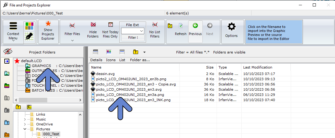
1. Open the File Explorer Window
2. If needed, select the Graphics Project Folder
3. Select the Graphic Filename
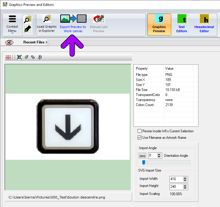
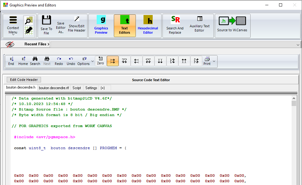
4. Graphic is opened in the Graphics PreviewWindow
5. If needed, adjust options like size, color reduction and orientation.
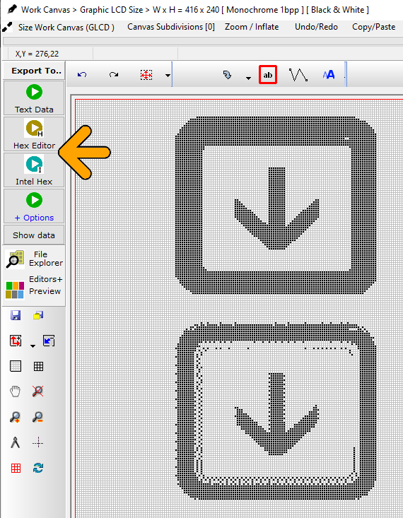
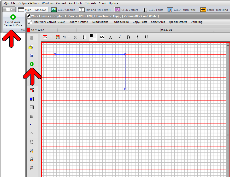
6. Export Preview to the Work Canvas( purple arrow )
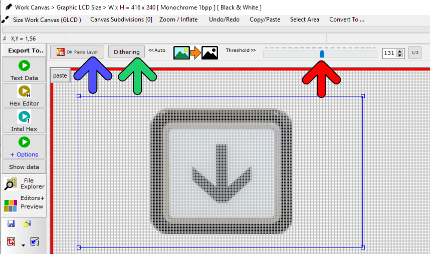
7. Graphic is inside the FLOATINGSELECTION LAYER, above the Work Canvas surrounded by a red frame
8. In this example, a conversion to monochrome is required. (monochrome GLCD)
9. Either choose Black and White THRESHOLD LEVEL with Adjustment Slider conversion or one of the DITHERING ALGORITHMS, like for example Floyd Steinberg.
10. If needed, drag the FLOATING SELECTION LAYER to its destination position on the canvas.
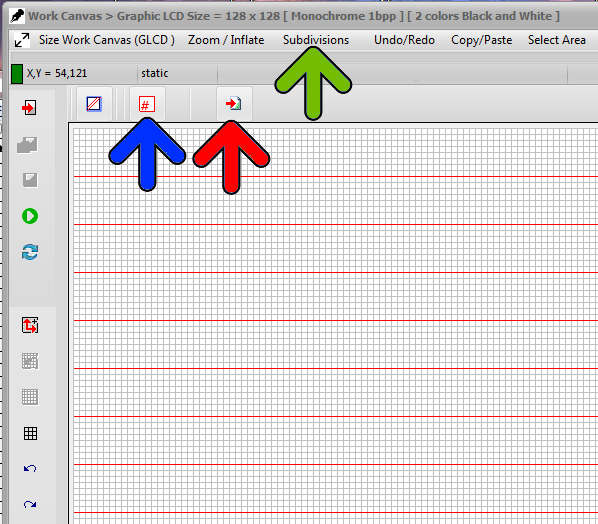
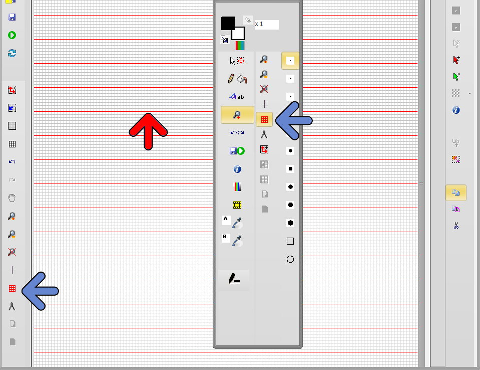
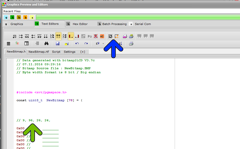
11. PASTE the selection layer to the WORK CANVAS ( blue arrow )
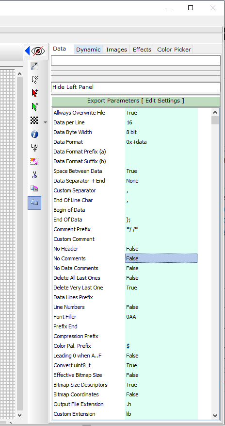
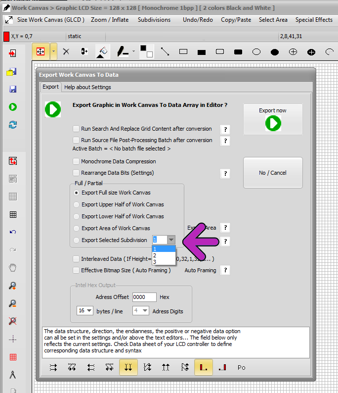
12. If needed, adjust the export parameters in the green column, Data Tab
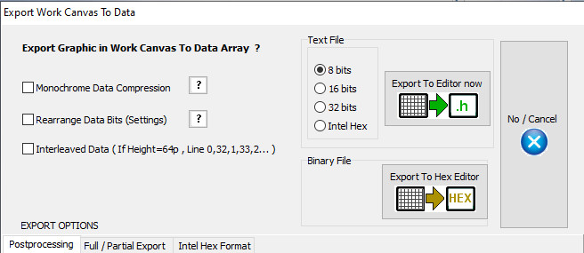
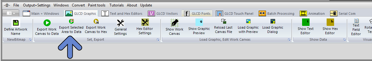
12. Export the Work Canvas to data array (Choose one of the Export Options : orange arrow)
13. Job done !
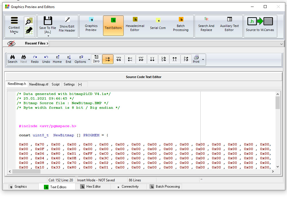
Note : With the 8 buttons with arrows at the top of the source code editor, adjust the data direction to match the display memory of the GLCD controller.
Bitmap2LCD is a tool for programming small Graphic LCDs in embedded systems.
Update V3.9H
A simple data compression feature, for the output of GLCD data arrays is implemented in Bitmap2LCD
This function is only available for monochrome mode and 8 bit output format.
The 8 bit microcontrollers for price sensitive projects are circuits with often less onchip memory space than most of the 16 or 32 bit devices.
The target is to save as many as microcontroller flash memory as possible. As tables for full display patterns of for example a 128 x 64 dot matrix LCD need 1024 bytes each, the goal of this function was to save flash space for more code or graphics or just to reduce the overall flash capacity and therefore to sink the price of the MCU chip.
The microcontroller firmware has to be able to handle these tables with a special code, which decodes the compressed data. Processing time for decompression has to be allowed.
How does it work ?
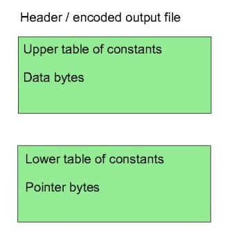
Instead of only converting the black and white pixels found in the work canvas to a linear list of n bytes, with the data compression method explained here, the data array is split into two separate arrays in one single output file : one as usual for the data stream and another for the pointers of each data groups.
The basic concept of this compression is based on making groups of consecutive identical data bytes in the data array.
Consecutive identical byte chains, and consecutive different byte chains are handled, the goal here is to save data bytes when a consecutive identical byte chain is found. While the first pointer of a consecutive different bytes chain is a loss of one data byte stored as a pointer, a consecutive identical byte chain of 10 bytes is a win of 8 bytes, the data being written only once in the data array. The count of them is then stored in the pointer byte array part.
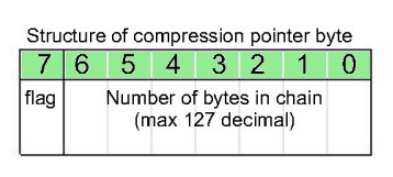
The maximum count of consecutive data, identical or different is limited to 127 ( pointer bits 6 to 0 ). If a data count in a group reaches 127, a new group is encoded.
The bit 7 of the pointer byte is the flag for the compression decoder. A 1 (high) is for a chain of identical data bytes, and a 0 (low) is for an chain of different data.
When data compression is active, Bitmap2LCD converts all data and shows the compression rate in the compression statistics at the end of the output file.
This method of compression shows different results in vertical or horizontal orientation conversion, it depends of the LCD graphic !
If possible, before to choose the LCD controller and its specific data orientation in Display RAM , you could try both orientations and compare the possible compression ratios.
In the Header Include file, the example script below shows how to setup the compression table information.
( It is an example for a GNU-C compiler for ATMEL AVR family )
Everything after the tag [&COMPRESSION] is a script information for the data compression function.
The tag [&CNAME] is replaced in the output table name, by the data array name
with an additional suffix _x ( For example : Newfile_x )
Export Graphic to Data array – Split Data in two parts in height
The export of the graphic inside the Work Canvas can be exported in two data arrays. The Height is split into two parts.
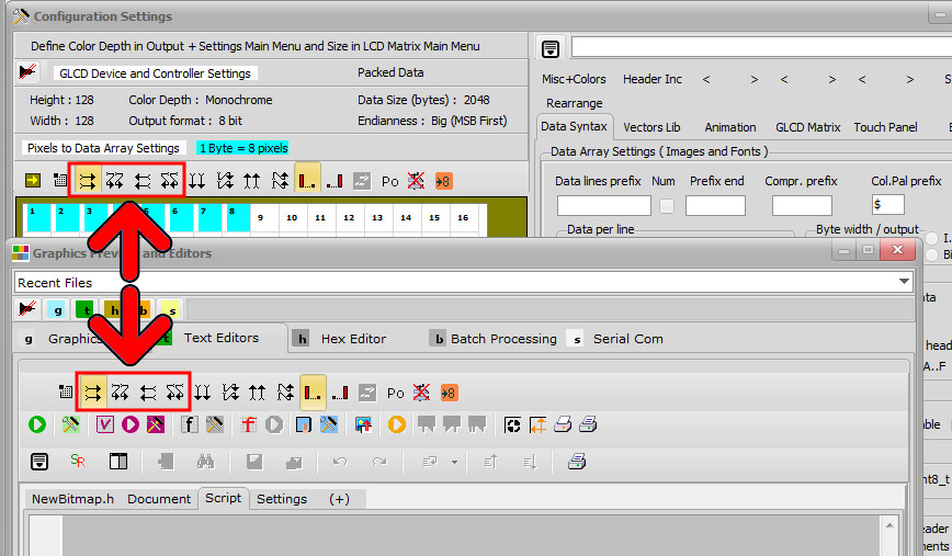
This only works in one of the horizontal data direction schemes, see red arrows below.
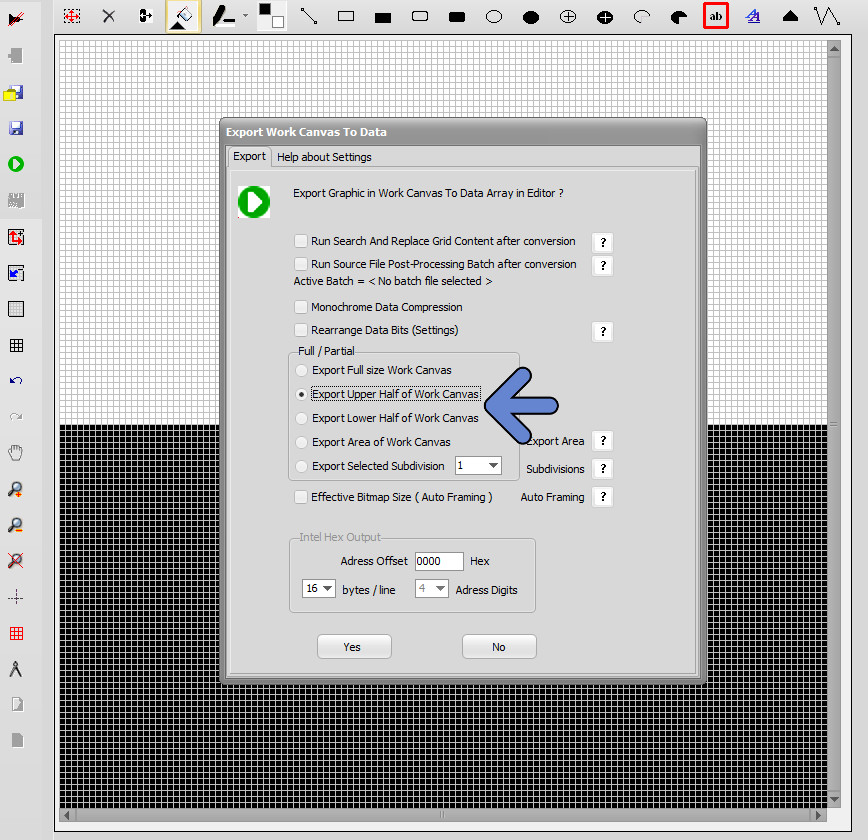
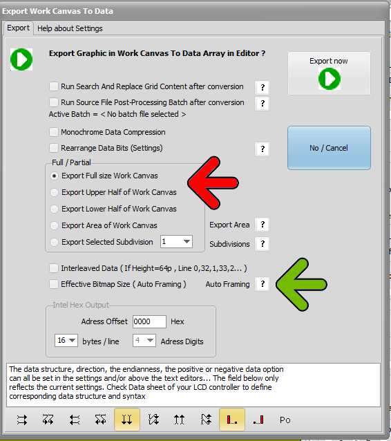
In the export Dialog below, there are two options (blue arrow) to export only the Upper or only the Lower half of the work canvas to a data array. In the example below, Upper half are all white pixels and Lower half are all black pixels.
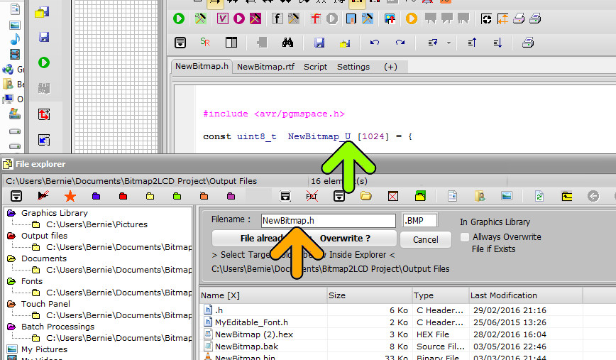
Once one of the upper half or the lower half data array has been exported, the filename must be manually modified in the dialog for example to Newbitmap_Upper or to Newbitmap_Lower to have two separate files inside the folder for the two GLCD halves.(orange arrow)
The variables names in the files are already different, if it’s an upper or a lower part data array (green arrow)
Bitmap2LCD is a tool for programming small Graphic LCDs in embedded systems and a programmable graphic and text processing tool.
Full Size or Partial Conversion of the Graphic in Work Canvas
Update V3.7c
Auto-framing (effective bitmap size) : The tool automatically builds a frame around the bitmap located inside the work canvas and converts only the pixels inside it to data.
This frame is built around the effective bitmap by ignoring all the pixels around that are considered as being in “background” color pixel. The background color is defined by the pixel color at X0 and Y 0 , at the top left corner.
The frame takes into account the number of pixels per byte ( In monochrome mode for example a multiple of 8 in height or in Width, this depends of the data direction )
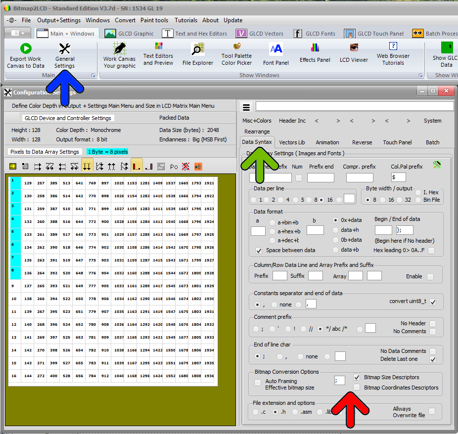
Bitmap Size Descriptors : If checked, at the end of the data array in the Text Editor , you will find descriptors with height and Width of the converted bitmap.
Bitmap Coordinates Descriptors : If checked, at the end of the data array in the Text Editor , you will find descriptors with X coordinate and Y coordinate of the converted bitmap, the coordinates of the top left corner. If checked, the Auto Framing processing is bidirectional. If unchecked, the Auto Framing processing will only be made in one direction.
Find these options in the configuration panel (blue arrow) Data syntax Tab (green arrow) in the Bitmap Conversion Options Group (red arrow)
Options when running a conversion of the graphic in the Work Canvas :
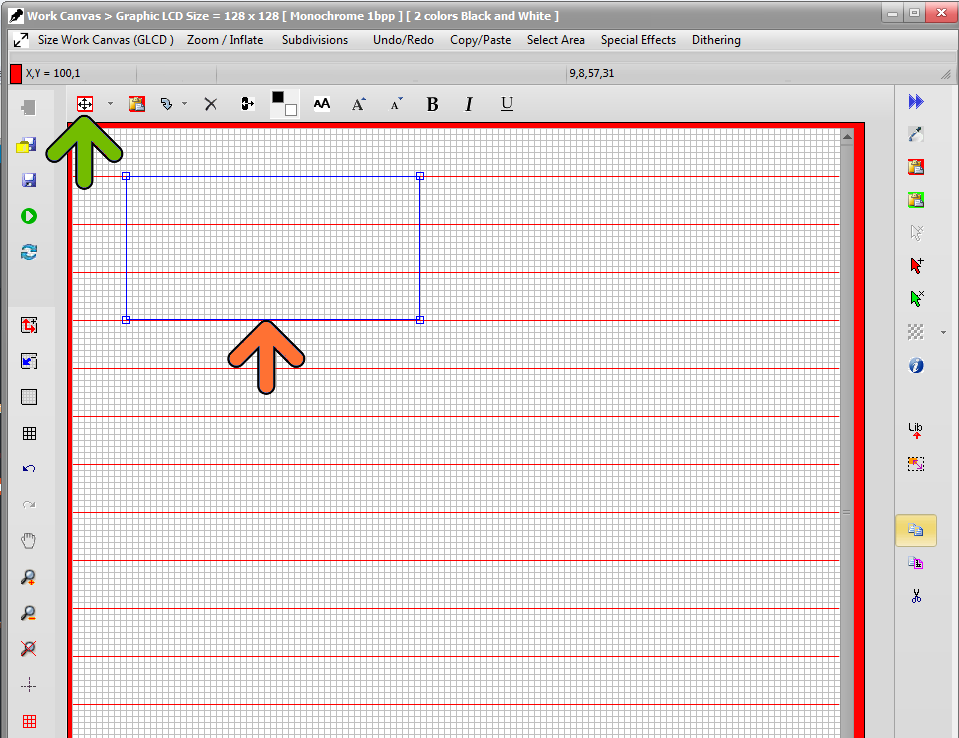
You can opt for an effective Bitmap Size (auto-framing) ( green arrow ) or for a conversion of the full size canvas or of a manually selected area of the Work Canvas ( red arrow )
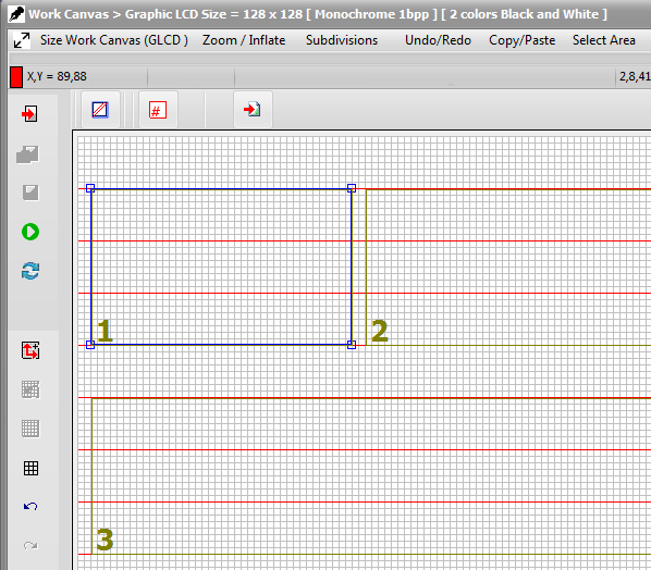
In the case of a manually selected area, you have then to select the area with the mouse along the paging scheme guide lines.
Intel HEX is a file format that conveys binary information in ASCII text form. It is commonly used for programming microcontrollers, EPROMs, and other types of programmable logic devices. ( Source : About Intel Hex )
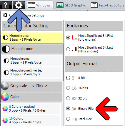
In the Output + Settings menu , there’s a new item, for the image inside the Work Canvas to be exported to Data as Intel Hex Files. (blue arrow)
There are several options located in the Start Conversion dialog to change the Intel Hex format.
Bitmap2LCD is a tool for programming small Graphic LCDs in embedded systems.
Output of the GLCD data array in a binary file
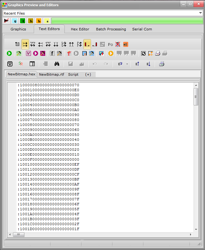
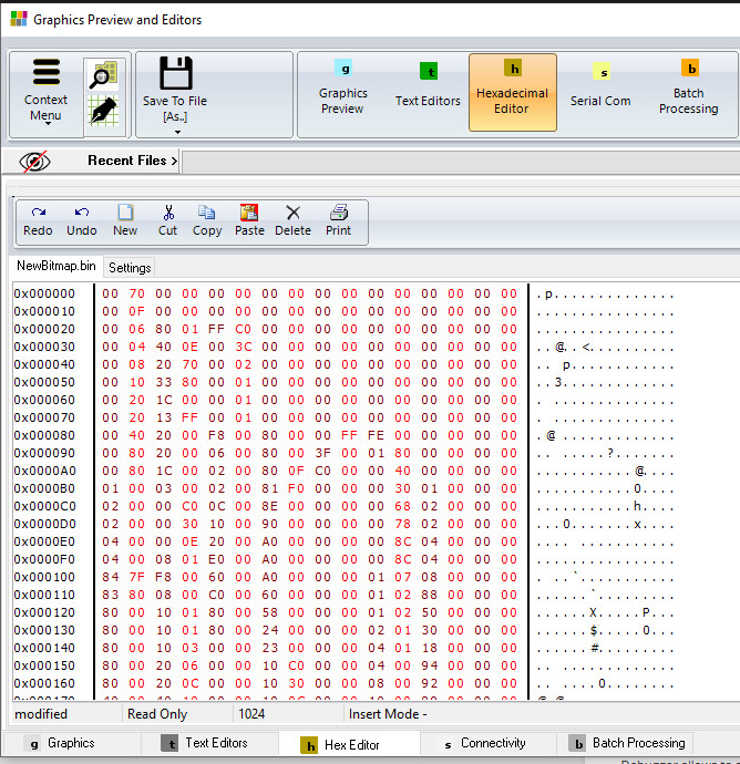
The converter data output feeds a built in hexadecimal editor and is saved to disk in a binary file (*.hex)
Output of the GLCD data array in a INTEL Hex format
Output of the GLCD data array in a text file for the compiler or assembler, format 8, 16 or 32 bit data
The converter data output feeds a built in text editor and can saved to disk in a text file
( *.c , *.h , *.asm , “.lib etc..)
Next to the data file, a rich text file (*.rtf) which contains all GLCD conversion parameters is written to disk, in the user defined “Documents folder”.
Bitmap2LCD is a tool for programming small Graphic LCDs in embedded systems.
This article is only for releases before V2.5
Let’s look how to configure the GLCD data output settings :
The generated data array file (orange arrow, in the picture below) can be configured to meet the syntax requests of your compiler or assembler. There are many possible settings, to make it possible to match the tool with most of the compilers of the market.
At first, you define the table data settings (red arrow)
Data Width format. ( 8,16 or 32 bits data)
Binary, Hex or decimal format.
Syntax of Data Byte/Word (make it compatible with your favorite compiler, assembler)
Type of file (extension)
As next, you define the header syntax (green arrow)
Click on the button and the header script is loaded into the editor. Modify it to meet your requirements.
When ready, quit the header editor by clicking the same button (green arrow at the right) or the quit button. (script is auto-saved)
Find more about the header syntax at the end of this article.
As next, you define the way the data arrays are arranged to correctly fit in the DDRAM of your LCD controller. These settings must be compatible with the LCD display functions in the GLCD Library you use in your project (blue arrow)
The origin corner X0,Y0
Data direction (The direction in which the pixels slices are taken from the work canvas and converted to GLCD data, for example in slices or in full canvas height or full canvas width. A slice is 8 pixels in monochrome mode and 2 pixels in 4bpp grayscale mode)
The Endianness (Most Significant Bit is first or last)
Special settings
More about File Header syntax (green arrow)
The script components [&***] can be included only once and will be replaced by the data or value when the data array is generated. Not needed script components can be erased.
[&NAME]
The [$NAME] and the image size and position are optional and can be placed optionally anywhere in the header.
[&SIZE]
Same for Size of Data
[&TRUEORG]
This is the script component if present in the file, to indicate that you want to have the XPOS and YPOS origins of a reduced dynamic table of constants ( a part of the display you want to change ) given from the X0,Y0 corner you selected in the table translation manager window.
[&XPOS]
[&YPOS]
[&WIDTH]
[&HEIGHT]
The corner position on the Work Canvas and the size of the converted graphic area can be exported into the file.
There are additional script components for font generation and data compression.
Export a part of a bitmap to GLCD data with Bitmap2LCD
Bitmap2LCD is a tool for programming small Graphic LCDs in embedded systems.
Update => V3.7c
With bitmap2LCD, you can easily convert a part of an image / picture to hex data for your Graphic LCD Display (partial conversion)
Export Selected Area button (in the main Menu)
To achieve this partial conversion, use the menu item Export Selected Area of to Data or follow this tutorial…
Enable the paging scheme display (one of the blue arrows)
Red horizontal or vertical lines will then appear in the Work Canvas (red arrow). These lines depend of the selected paging scheme (horizontal or vertical) and of the pixel data depth ( monochrome , grayscale… ) In this monochrome example, we have 8 pixels / data byte, therefore a gap 8 pixels between the lines.
These lines will also act as area delimiters / selection magnets when you later select the area to convert.
With the selection tool (green arrow) , and with the mouse clicked in the Work Canvas, define the area frame (orange arrow)
If you want to see or include somewhere the X and Y corner position, the width and the height of the area frame (orange arrow) inside the code (green arrow) set the buttons (blue arrow). You can also specify the use of these 4 informations within the header include editor.