Bitmap2LCD is a tool for programming small Graphic LCDs in embedded systems and a programmable graphic and text processing tool.
Export a Graphic to a GLCD Data Array
Update V4.6c
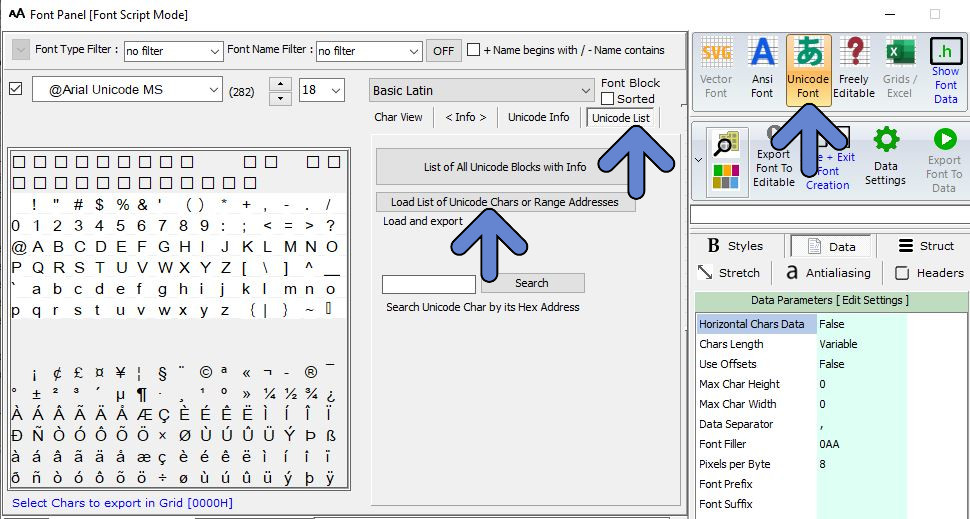
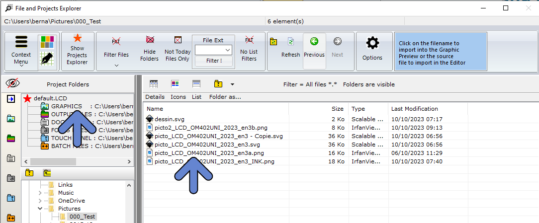
1. Open the File Explorer Window
2. If needed, select the Graphics Project Folder
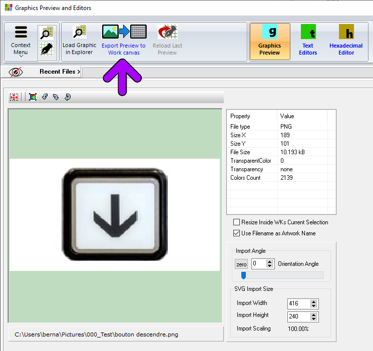
3. Select the Graphic Filename
4. Graphic is opened in the Graphics PreviewWindow
5. If needed, adjust options like size, color reduction and orientation.
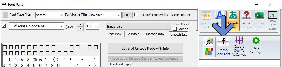
6. Export Preview to the Work Canvas( purple arrow )
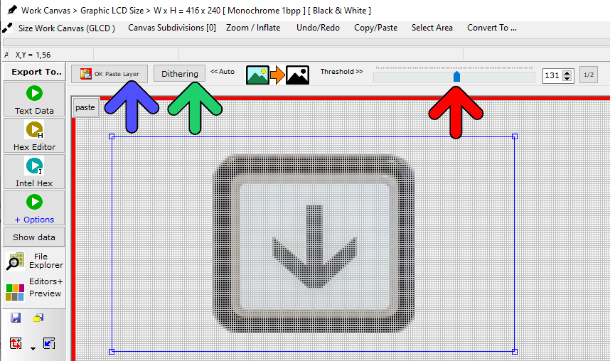
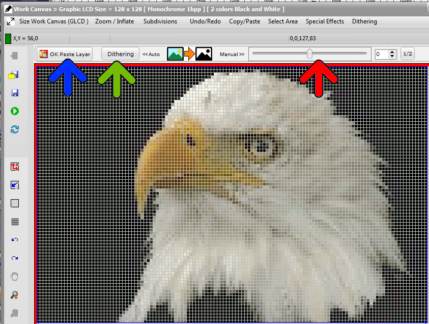
7. Graphic is inside the FLOATINGSELECTION LAYER, above the Work Canvas surrounded by a red frame
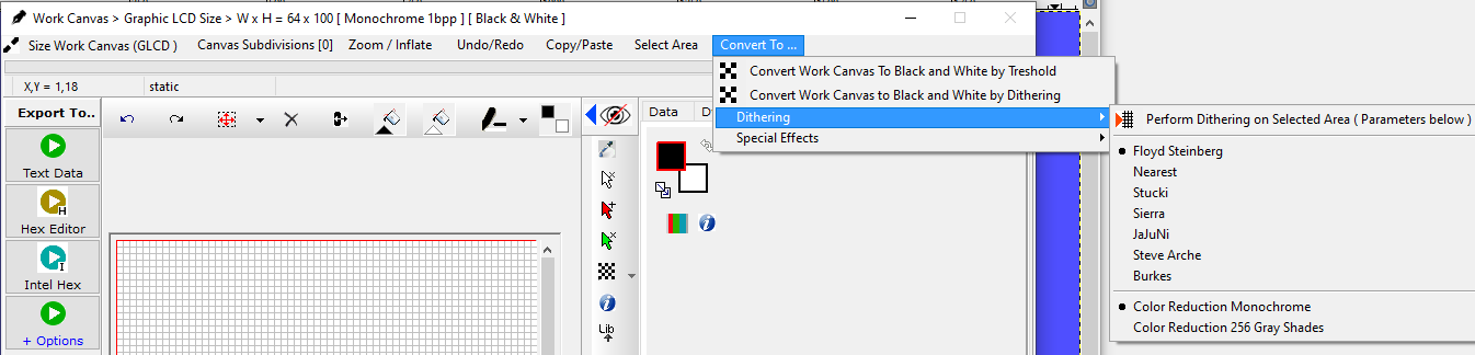
8. In this example, a conversion to monochrome is required. (monochrome GLCD)
9. Either choose Black and White THRESHOLD LEVEL with Adjustment Slider conversion or one of the DITHERING ALGORITHMS, like for example Floyd Steinberg.
10. If needed, drag the FLOATING SELECTION LAYER to its destination position on the canvas.
11. PASTE the selection layer to the WORK CANVAS ( blue arrow )
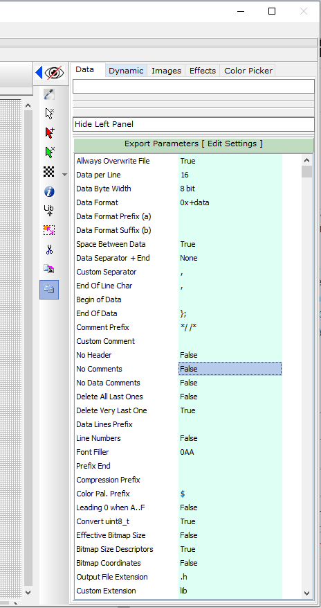
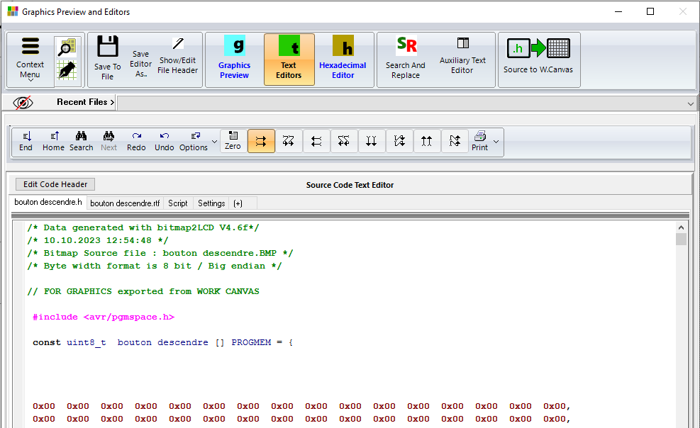
12. If needed, adjust the export parameters in the green column, Data Tab
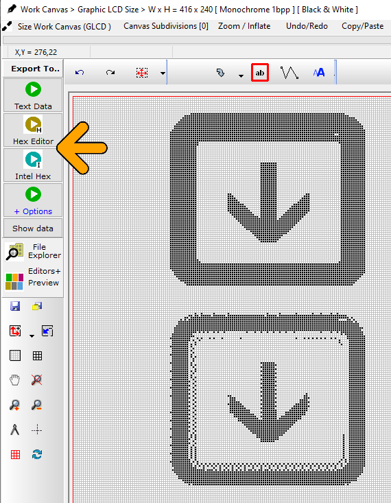
12. Export the Work Canvas to data array (Choose one of the Export Options : orange arrow)
13. Job done !
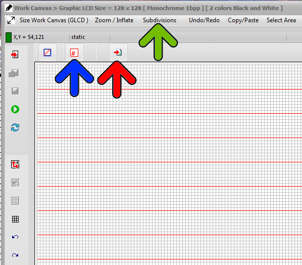
Note : With the 8 buttons with arrows at the top of the source code editor, adjust the data direction to match the display memory of the GLCD controller.
Bitmap2LCD is a programmingtool for small Graphic LCDs in embedded systems.
Project Folders and Project Management
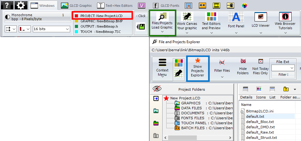
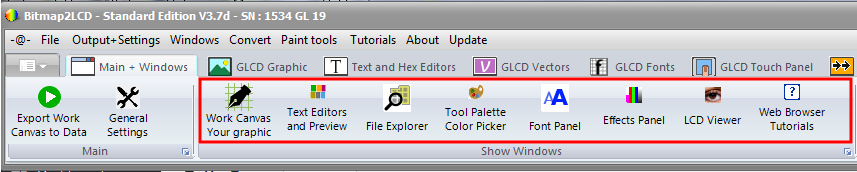
The current active project is displayed in the Windows Tab of the Main Menu (red frame) By clicking in this area, you have direct access to the Project Manager. There’s originally only 1 project called default.LCD
You can add other projects to the system. Every project is a separate set of settings, project folders, work canvas sizes etc.. To access the Project Manager, click on the Files/Projects Button (green frame) then Show Projects Explorer on the File explorer Window (blue frame)
The File explorer Window
The field at the top left side of the file explorer is the “Project Folders Management” and “the Project Management”.
With the buttons showing colored folder icons at the right side of the below blue arrow, you can define the folders where you want to convert, find and save the files of the current project.
By clicking on one of these colored folder icons, you define the currently active folder in the tree as the project folder for Graphics, Output files, Project Documents, Fonts or Touch Screen files.
When clicking on the links inside the field, you have a quick access to the different project folders.
When for example clicking on “Graphics Library“, you switch the File List Filter to “all graphic files” excluding the other files type from the list. (This behavior can be enabled or disabled in the Filter pop-up menu)
These project folders and all the configuration settings (GLCD size, Data Direction, File Header etc..) are saved to the disk as a set of project settings.
By clicking on the Show Projects Explorer button (orange star icon) in the menu bar (blue arrow) you can switch the view to the project management.
The Project Manager
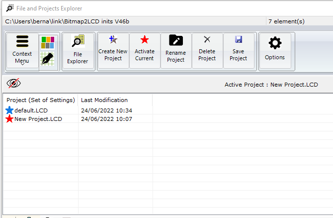
The Project list shows the list of available projects. The list can be void in the case only the default project exists. Otherwise, like in this example, the list shows and the active project is marked with a red arrow. The other projects are marked with blue arrows.
The files attached to a project are are located in the documents/bitmap2LCD inits(version) folder.
With the Buttons in the Menu Bar at the top of the project list, you can Create, Activate, Rename and delete Projects.
>.<
Import Projects from previous versions
Copy the project files attached to a previous Project from the documents/bitmap2LCD inits(previous version) folder to the documents/bitmap2LCD inits(current version) folder.
Bitmap2LCD is a software tool for programming small Graphic LCDs in embedded systems and a programmable text and graphic processing tool.
Shades of Gray
Update V4.7b
Bitmap2LCD supports the export data arrays for grayscale Graphic LCD.
The choice is 4 , 16, 32 or 256 gray levels.
Configuration settings
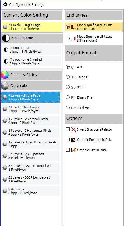
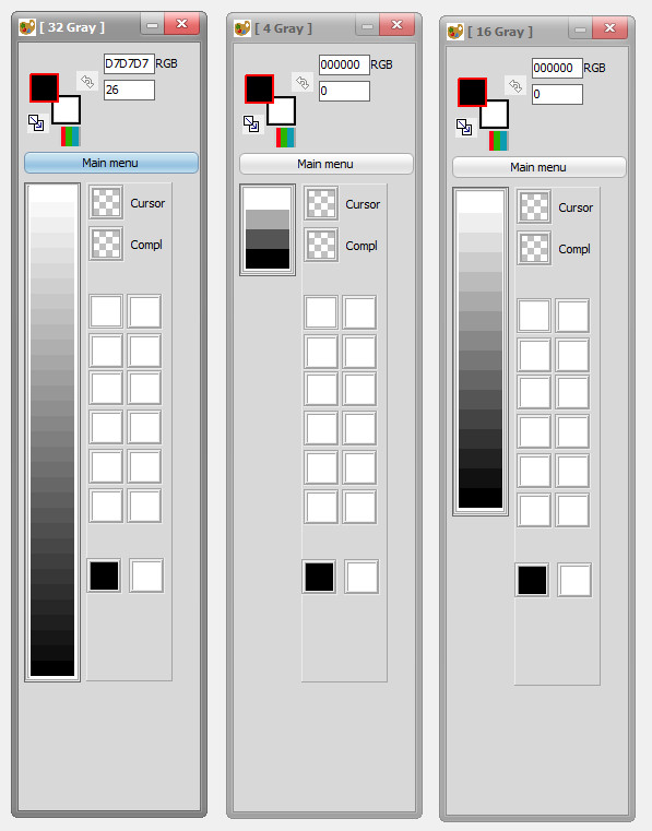
Color pickers for 32, 4 and 16 shades of gray modes :
Example, in the 32 gray levels mode, the shades between the white color to the black color will output data per pixel from 0 to 31 decimal, or the opposite, from 31 to 0 decimal if you enable the Invert Grayscale Palette Parameter checkbox.
Bitmap2LCD is a tool for programming small Graphic LCDs in embedded systems and a programmable graphic and text processing tool.
Export Font Data to Binary File : Data Structure
Standard Edition , Update V4,0
When you export the Font Script to a Binary File, the data array is sent to the Hex Editor and saved as a .hex to Disk. ( For example for Data storage in EEprom )
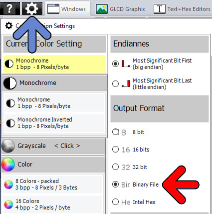
Output + Settings Main Menu :
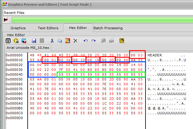
See below the data structure inside the Hex Editor.
In the following example the generated Font is Arial Unicode Size 10 , ANSI, Selected Chars are AB and C
Structure :
1st Line , red area 00 03 = Number of chars (decimal)
2nd Line, Character Info between 55 AA …. AA 55
00 01 Type of Font >> 0001 = ANSI >> 0002 = UNICODE >> 0003 Editable Font
00 36 Char Data Count (decimal)
00 10 Char Width (decimal)
00 18 Char Height (decimal)
00 2D Char ASCII ( Optional > ANSI, Editable font ) or Unicode Char Address (hex)
00 50 First Address Next Char (hex)
Blue Area = Char Pixels data
Green Area = Data Filler, Forces next Char to begin from line begin
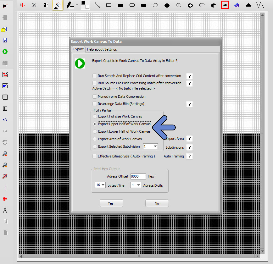
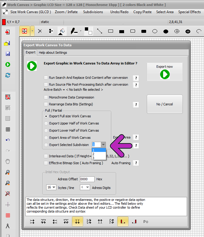
Export Graphic to Data array – Split Data in two parts in height
The export of the graphic inside the Work Canvas can be exported in two data arrays. The Height is split into two parts.
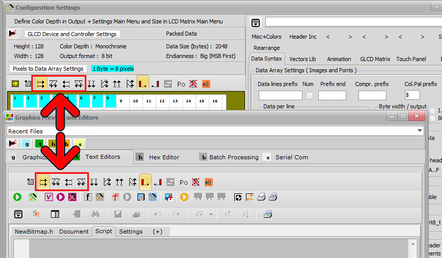
This only works in one of the horizontal data direction schemes, see red arrows below.
In the export Dialog below, there are two options (blue arrow) to export only the Upper or only the Lower half of the work canvas to a data array. In the example below, Upper half are all white pixels and Lower half are all black pixels.
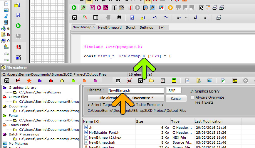
Once one of the upper half or the lower half data array has been exported, the filename must be manually modified in the dialog for example to Newbitmap_Upper or to Newbitmap_Lower to have two separate files inside the folder for the two GLCD halves.(orange arrow)
The variables names in the files are already different, if it’s an upper or a lower part data array (green arrow)
Bitmap2LCD is a tool for programming small Graphic LCDs in embedded systems.
Bitmap2LCD Appearance, Windows and Styles
Update V3.7c
The program is a “floating windows application” and supports dual screen
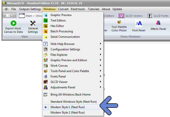
Then you can also choose between the skins called “Original Windows Style” or “Modern Style”
You can choose your favorite Windows skin at the top of the Windows Main Menu (blue arrow) which will only be effective at the next application launch.
Bitmap2LCD supports dual monitors, and sometimes a window can be entirely hidden or located somewhere on the secundary window or even outside the monitor surfaces. You can bring back “home” (on the main screen) a window by clicking the dedicated menu items.
Bitmap2LCD is a tool for programming small Graphic LCDs in embedded systems and a programmable graphic and text processing tool.
Full Size or Partial Conversion of the Graphic in Work Canvas
Update V3.7c
Auto-framing (effective bitmap size) : The tool automatically builds a frame around the bitmap located inside the work canvas and converts only the pixels inside it to data.
This frame is built around the effective bitmap by ignoring all the pixels around that are considered as being in “background” color pixel. The background color is defined by the pixel color at X0 and Y 0 , at the top left corner.
The frame takes into account the number of pixels per byte ( In monochrome mode for example a multiple of 8 in height or in Width, this depends of the data direction )
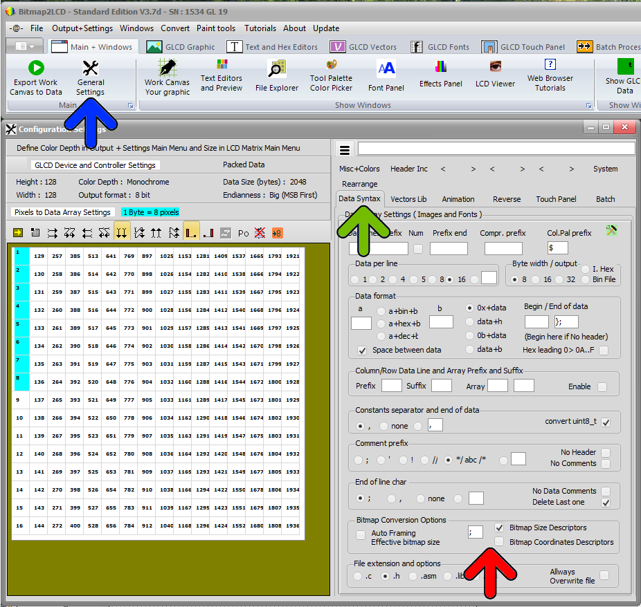
Bitmap Size Descriptors : If checked, at the end of the data array in the Text Editor , you will find descriptors with height and Width of the converted bitmap.
Bitmap Coordinates Descriptors : If checked, at the end of the data array in the Text Editor , you will find descriptors with X coordinate and Y coordinate of the converted bitmap, the coordinates of the top left corner. If checked, the Auto Framing processing is bidirectional. If unchecked, the Auto Framing processing will only be made in one direction.
Find these options in the configuration panel (blue arrow) Data syntax Tab (green arrow) in the Bitmap Conversion Options Group (red arrow)
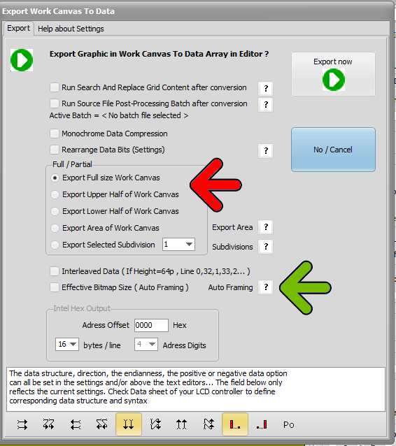
Options when running a conversion of the graphic in the Work Canvas :
You can opt for an effective Bitmap Size (auto-framing) ( green arrow ) or for a conversion of the full size canvas or of a manually selected area of the Work Canvas ( red arrow )
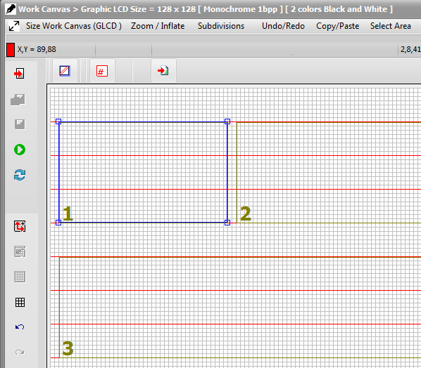
In the case of a manually selected area, you have then to select the area with the mouse along the paging scheme guide lines.