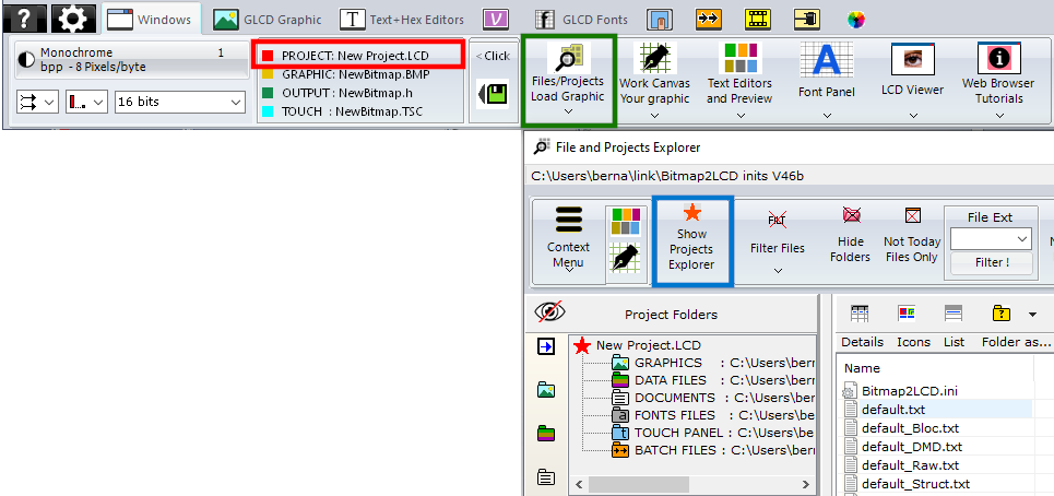
About : Font panel and font generator data structures
Font Panel ( SVG / ANSI / UNICODE and Editable Fonts )
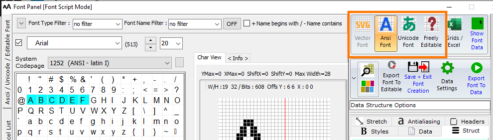
4 different font categories are available : ANSI and Unicode international System fonts (installed on Windows) , the SVG fonts (for grayscale 256) based on vector graphics for a better anti-aliasing quality, and Freely Editable Font, for customized bitmap glyphs.
^
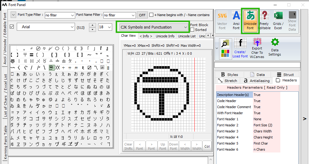
Unicode block selection (green frame)
Font Panel ( EDITABLE Font )
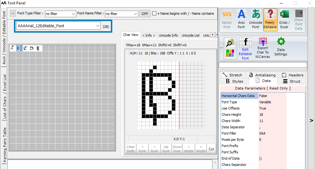
An Editable Font can be an import of a system font + edits or created from scratch.
In this example only 5 chars
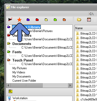
List of the existing Editable Fonts (blue frame)
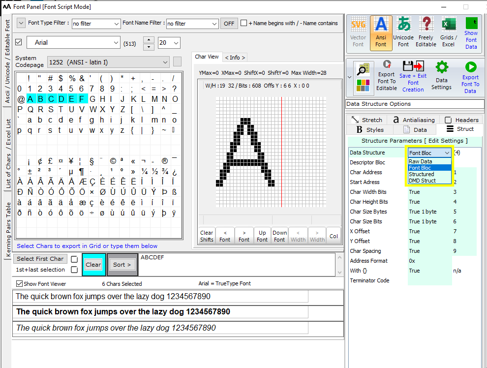
Font Panel ( ANSI Font )
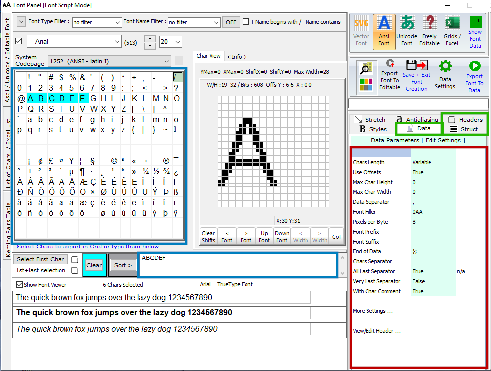
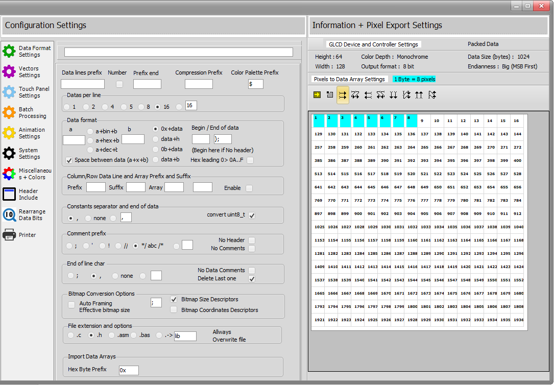
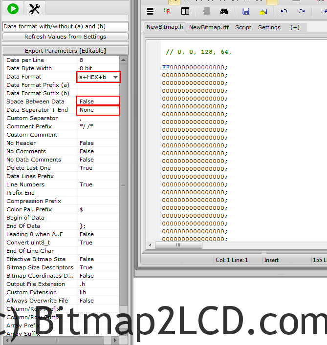
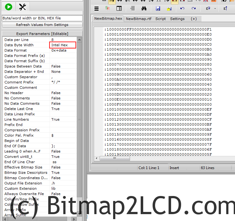
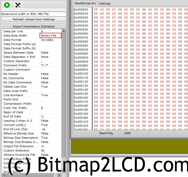
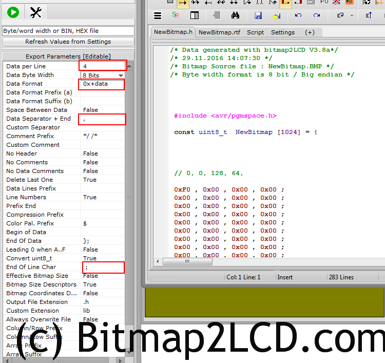
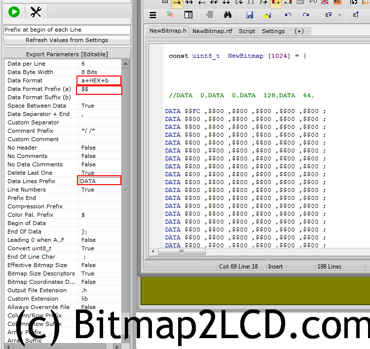
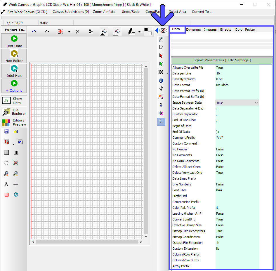
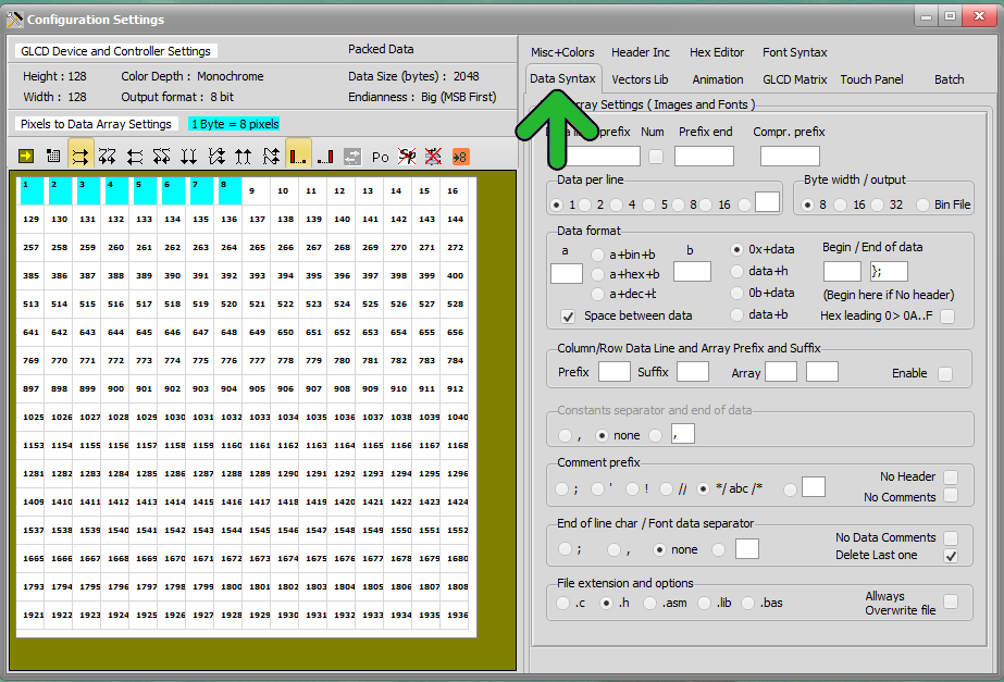
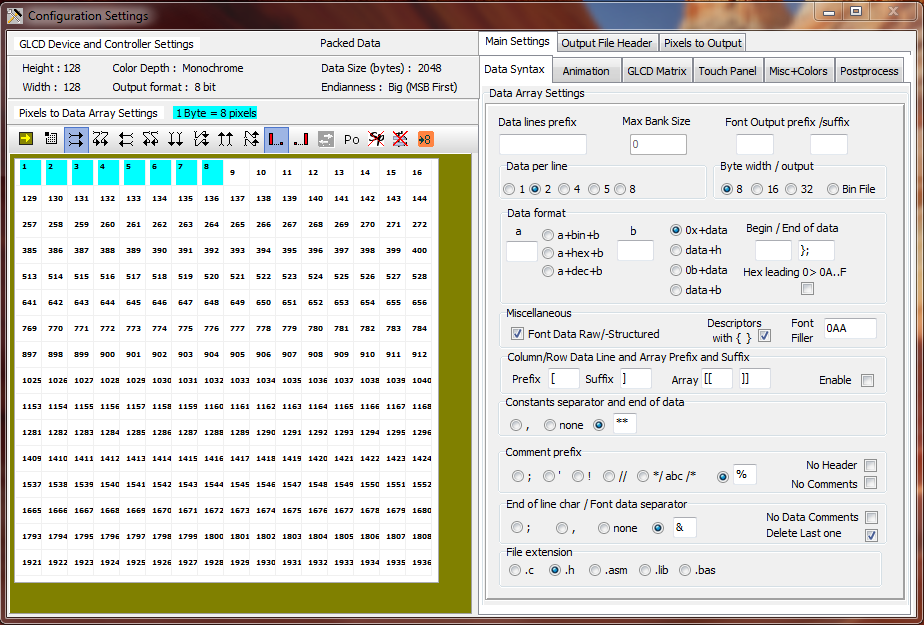
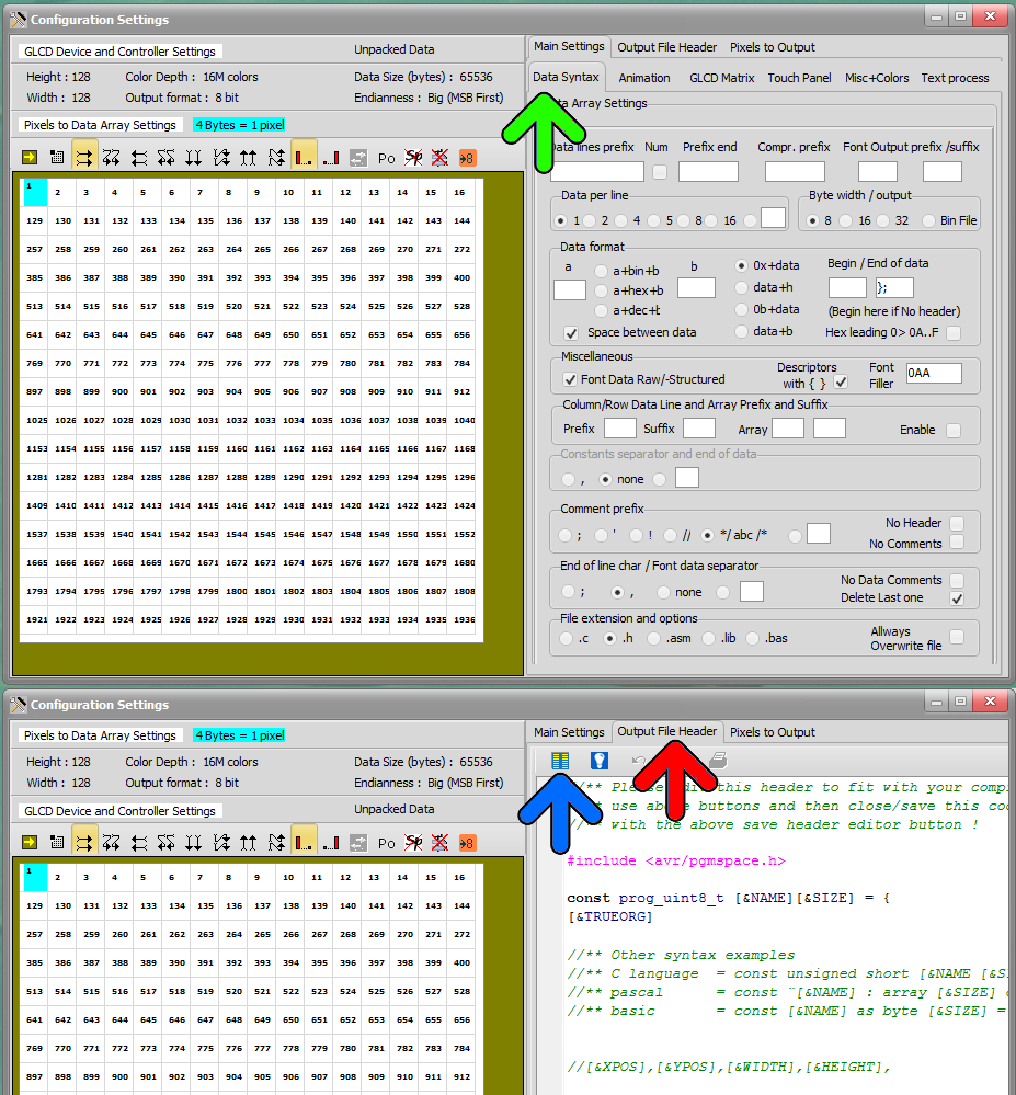
Font Settings in 3 panels : Structure, Header, and Data (green frames)
The parameters can be edited (when green background) in these 3 fields (red frame)
The chars selected in the Grid (blue frame) will be exported to data
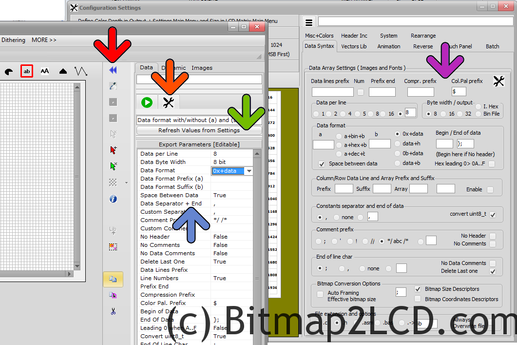
Font panel > Structure Parameters
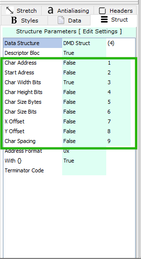
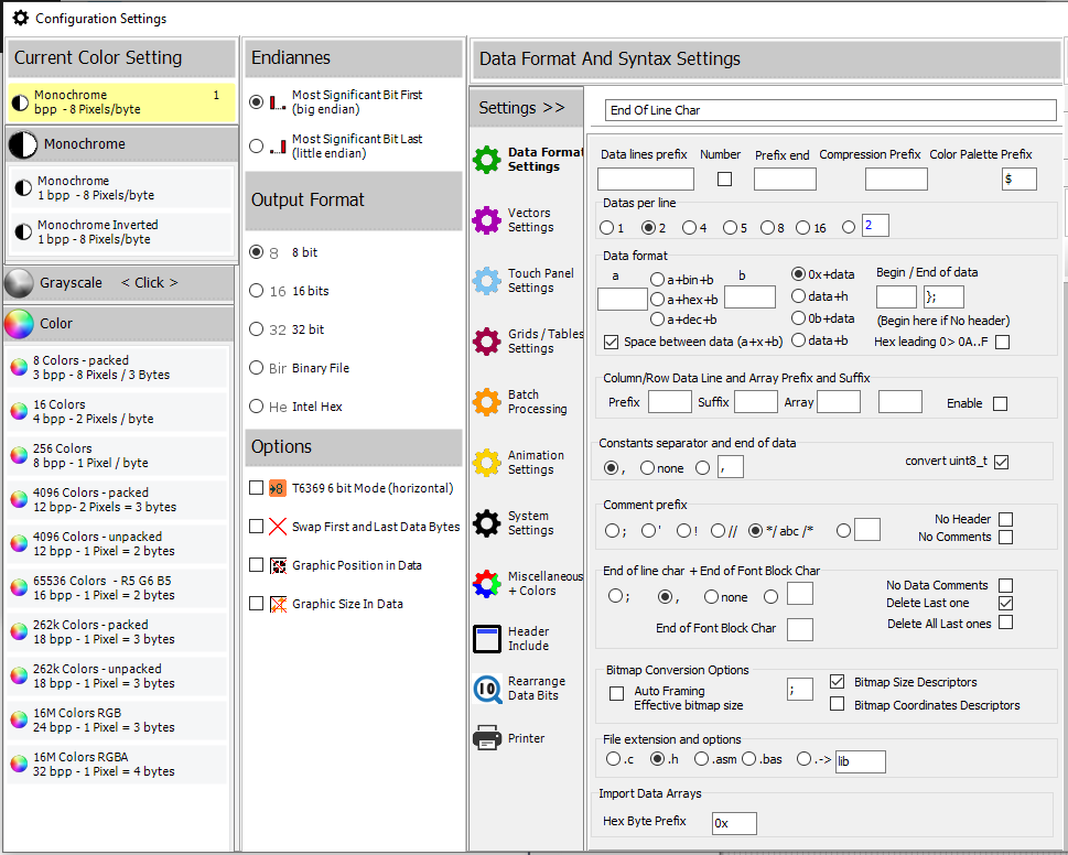
The Parameters in the green frame are separated for each Data Structure (1st Parameter of this list) These data are then present or not in the Descriptor blocs of the output data.
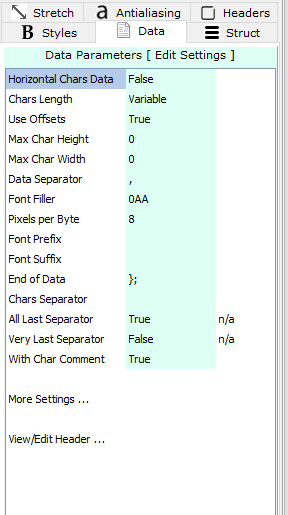
Font panel > Data Parameters
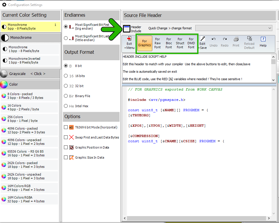
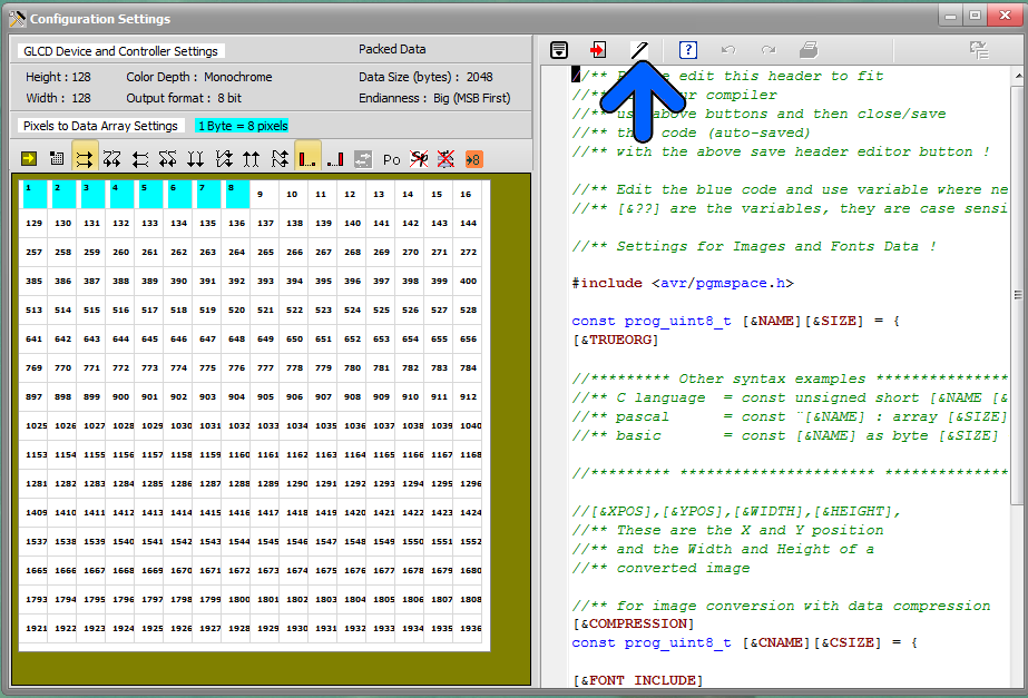
Font panel > Headers Parameters
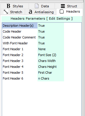
The font headers such as the description and the font header code exported at the top of the data output.
Font panel > Font Data Structure
>.<
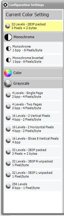
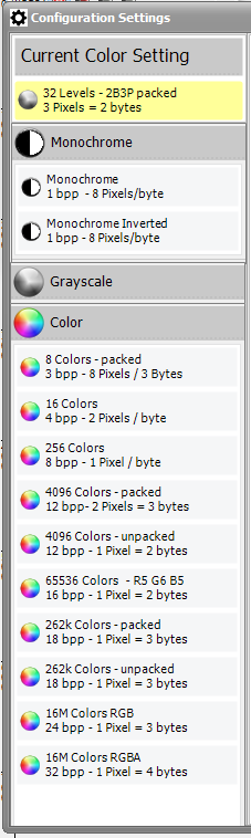
Data Structures :
Raw Data, Font Bloc, Structured and DMD struct are different outputs layouts for fonts.
The differences in headers, bitmap glyphs and descriptors
Example for “RAW Data” structure
Optional descriptors at the end
/* >>> Code Header */
/* ( Bitmap Glyphs ) */
/* @ 0 Char:’A’ Width in bits :10 */
0x08 , 0x00 , /* ____#___________ */
0x14 , 0x00 , /* ___#_#__________ */
0x14 , 0x00 , /* ___#_#__________ */
0x14 , 0x00 , /* ___#_#__________ */
0x22 , 0x00 , /* __#___#_________ */
0x22 , 0x00 , /* __#___#_________ */
0x7F , 0x00 , /* _#######________ */
0x41 , 0x00 , /* _#_____#________ */
0x80 , 0x80 , /* #_______#_______ */
0x80 , 0x80 , /* #_______#_______ */
/* @ 20 Char:’B’ Width in bits :10 */
0x7E , 0x00 , /* _######_________ */
0x41 , 0x00 , /* _#_____#________ */
0x41 , 0x00 , /* _#_____#________ */
0x41 , 0x00 , /* _#_____#________ */
0x7E , 0x00 , /* _######_________ */
0x41 , 0x00 , /* _#_____#________ */
0x41 , 0x00 , /* _#_____#________ */
0x41 , 0x00 , /* _#_____#________ */
0x41 , 0x00 , /* _#_____#________ */
0x7E , 0x00 /* _######_________ */
};
const uint8_t Arial_10_1252_(ANSI_-_latin_I)_Descriptors[][] PROGMEM = {
{0x41,0,10,10,100,160,0,30}, /* ‘A’ */
{0x42,20,10,10,100,160,0,30} /* ‘B’ */
>.<
Example for “Font BLOC” data structure
Optional Font Header at the top
Optional descriptors at the top of every bitmap glyph
const unsigned char Arial_10_1252_(ANSI_-_latin_I)_Bitmaps[] = {)
0x00,0x3E,13,16,0x00,2, (font header)
/* ‘A’ */
0x41,0,10,10,100,160,0,30,
0x08 , 0x00 , /* ____#___________ */
0x14 , 0x00 , /* ___#_#__________ */
0x14 , 0x00 , /* ___#_#__________ */
0x14 , 0x00 , /* ___#_#__________ */
0x22 , 0x00 , /* __#___#_________ */
0x22 , 0x00 , /* __#___#_________ */
0x7F , 0x00 , /* _#######________ */
0x41 , 0x00 , /* _#_____#________ */
0x80 , 0x80 , /* #_______#_______ */
0x80 , 0x80 , /* #_______#_______ */
/* ‘B’ */
0x42,20,10,10,100,160,0,30,
0x7E , 0x00 , /* _######_________ */
0x41 , 0x00 , /* _#_____#________ */
0x41 , 0x00 , /* _#_____#________ */
0x41 , 0x00 , /* _#_____#________ */
0x7E , 0x00 , /* _######_________ */
0x41 , 0x00 , /* _#_____#________ */
0x41 , 0x00 , /* _#_____#________ */
0x41 , 0x00 , /* _#_____#________ */
0x41 , 0x00 , /* _#_____#________ */
0x7E , 0x00 /* _######_________ */
};
>.<
Example for *Structured” data structure
Bitmap glyphs in blocks, Descriptors in blocks at the end
/* >>> Code Header */
/* ( Bitmap Glyphs ) */
static const uint8_t image_data_Arial_10_1252_(ANSI_-_latin_I)_0x41[20] =
{
0x08 , 0x00 , /* ____#___________ */
0x14 , 0x00 , /* ___#_#__________ */
0x14 , 0x00 , /* ___#_#__________ */
0x14 , 0x00 , /* ___#_#__________ */
0x22 , 0x00 , /* __#___#_________ */
0x22 , 0x00 , /* __#___#_________ */
0x7F , 0x00 , /* _#######________ */
0x41 , 0x00 , /* _#_____#________ */
0x80 , 0x80 , /* #_______#_______ */
0x80 , 0x80 /* #_______#_______ */
};
static const uint8_t image_data_Arial_10_1252_(ANSI_-_latin_I)_0x42[26] =
{
0x7E , 0x00 , /* _######_________ */
0x41 , 0x00 , /* _#_____#________ */
0x41 , 0x00 , /* _#_____#________ */
0x41 , 0x00 , /* _#_____#________ */
0x7E , 0x00 , /* _######_________ */
0x41 , 0x00 , /* _#_____#________ */
0x41 , 0x00 , /* _#_____#________ */
0x41 , 0x00 , /* _#_____#________ */
0x41 , 0x00 , /* _#_____#________ */
0x7E , 0x00 /* _######_________ */
};
/* >>> Optional Char Descriptors */
/* ( Char Adress Start adress Width in bits Height in bits Char Bytes Size in bits X Offset Y Offset Char Spacing bits ) */
static const tImage Arial_10_1252_(ANSI_-_latin_I)_array_[] = {
// character : ‘A’
{0x41,0,10,10,100,160,0,30 , &Arial_10_1252_(ANSI_-_latin_I)_0x41},
// character : ‘B’
{0x42,20,10,10,100,160,0,30 , &Arial_10_1252_(ANSI_-_latin_I)_0x42}
};
const tfont Arial_10_1252_(ANSI_-_latin_I) = { 2 , Arial_10_1252_(ANSI_-_latin_I)_array };
>.<
Example for “DMD Struct” data structure
Optional Font Header at the top
Descriptors in blocks at the top (Here widths only )
static const uint8_t Arial_10_1252_(ANSI_-_latin_I)_Bitmaps[2][] PROGMEM = {
0x00,0x30,13,16,0x00,2, (font header)
/* >>> Code Header */
/* ( Width in bits ) */
10, /* ‘A’ */
10 /* ‘B’ */
,
/* ( Bitmap Glyphs ) */
/* @ 0 Char:’A’ Width in bits :10 */
0x08 , 0x00 , /* ____#___________ */
0x14 , 0x00 , /* ___#_#__________ */
0x14 , 0x00 , /* ___#_#__________ */
0x14 , 0x00 , /* ___#_#__________ */
0x22 , 0x00 , /* __#___#_________ */
0x22 , 0x00 , /* __#___#_________ */
0x7F , 0x00 , /* _#######________ */
0x41 , 0x00 , /* _#_____#________ */
0x80 , 0x80 , /* #_______#_______ */
0x80 , 0x80 , /* #_______#_______ */
/* @ 20 Char:’B’ Width in bits :10 */
0x7E , 0x00 , /* _######_________ */
0x41 , 0x00 , /* _#_____#________ */
0x41 , 0x00 , /* _#_____#________ */
0x41 , 0x00 , /* _#_____#________ */
0x7E , 0x00 , /* _######_________ */
0x41 , 0x00 , /* _#_____#________ */
0x41 , 0x00 , /* _#_____#________ */
0x41 , 0x00 , /* _#_____#________ */
0x41 , 0x00 , /* _#_____#________ */
0x7E , 0x00 /* _######_________ */
};