Tag Archives: bitmap2lcd

Bitmap2LCD Software Update

Bitmap2LCD is a tool for programming small Graphic LCDs in embedded systems and a programmable graphic and text processing tool.

Standard and Extended Editions can automatically be updated by the user.

From version V3.9H

1. Click the [ ? ] button at the left of the main menu : The About window is showed.

2. Update tab , check latest and current versions.

3. If active, Download and Install Latest …

4.The current version installs the update.

5.The current version will not be uninstalled !

6. You’ll find both the current and latest versions as icons on the desktop.

>.<

Text Processing Automation Tool

Bitmap2LCD is a tool for programming small Graphic LCDs in embedded systems and a programmable text processing tool.

Text Processing Automation Tool

( Function described here was updated from Bitmap2LCD V2.8a  , and is available with the Standard Edition license )

One of the various features included in the bitmap2LCD GLCD toolbox is the Source Code / Text file processing.

To find and replace text in many files or if it is needed to search and replace different data 100+ times at once, or to proceed to many other text processing tasks , the Bitmap2LCD tool will help you saving precious time to search and replace text in the blink of an eye.

You can program batch scripts of your repetitive text-processing tasks such as auto-replacement or/and auto-insertion of any text in your source code, save it to the disk (.SPP) and define it as the current active batch of a project.

The list of functions in the batch script makes it possible to search automatically for text strings within the code and based on the paired actions, decide whether the alternative text string shall overwrite the text string searched for, or be placed after it.

 Here’s the list of the functions available in the bitmap2LCD text processing tool

( Note : Addition of new functions in the future , also see blue arrow below in fig1. )

List of the conditions and modal switches

if ‘text’

if not ‘text’

while ‘text’

if line number(index)

if last line

if flag

if not flag

and ‘text’

and flag

and not ‘text’

and not flag

or ‘text’

or flag

or not ‘text’

or not flag

begin of loop

end of loop

search back from line end

search from line begin

case sensitive on

case sensitive off

..

List of the functions

then set flag

then reset flag

then insert (index)’text’

then overwrite (index)’text’

then remove ‘text’

then delete until ‘text’

then get integer (index)

then get hex (index)

then get float (index)

then insert integer (index)

then insert hex (index)

then insert float (index)

then next line

then delete line

then insert line

then save as ‘file’

then start copy

then stop copy

then start delete

then stop delete

then save copy as ‘file’

then load and insert ‘file’

etc..

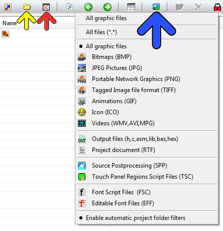
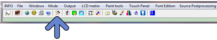
To program a batch , click Edit Current Batch or click New batch ( buttons are located in the main menu )
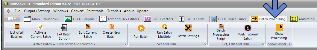
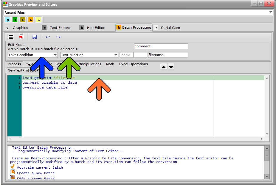
bitmap2lcd-batch-processing-menu

bitmap2lcd-batch-processing_3

fig. 1

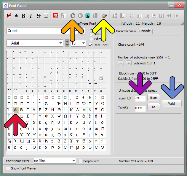
Then choose the conditional function in the Function combo box (blue arrow)

You can’t directly edit the text itself in the editor, but you can move the green cursor up and down in the program (orange arrow) and edit the index , text and comment fields of the line selected by the cursor, in the fields at the top of the editor (green arrow).

Note that the index field can be left at ‘index’ when the cursor position is not known nor fixed : Index is a numeric field , a cursor position of character or text or if left at ‘index’, it will be the cursor position where the searched ‘text’ was found in the conditional instruction before (‘if’) .

An IF followed by one or more THEN is a pass thru the whole text file loaded in the Text Editor (second tab fig1. ) Please remember that every IF + Then(s) Pair is a new pass from the top to the end of the text file.

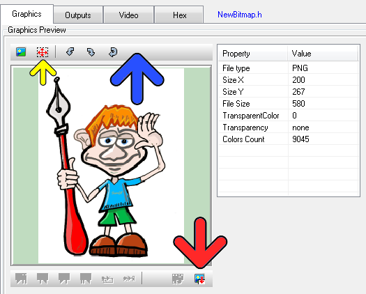
In the above examples in fig1. and fig2 , a part of the file is copied in another file named copy3.txt located in the folder defined as output files folder .
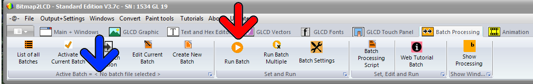
bitmap2lcd-batch-processing-menu_2

fig 2.

The Processing batch can be started from the user interface, from a single button (see red arrow) or from a main menu item.

See also the article about the automatic post-processing in this topic.

Re-installing or uninstalling Bitmap2LCD

Bitmap2LCD is a tool for programming small Graphic LCDs in embedded systems.

Re-installing or uninstalling Bitmap2LCD

Up to Version V2.8a (b8) , the folder where your personal tool configuration and all your projects were saved, was’nt automatically deleted when running the uninstall task. This has changed since.

in the Documents folder : see folder Bitmap2LCD inits

If you have an anterior version and want for any reason to uninstall the software, or reinstall it completely, you can just delete this Bitmap2LCD inits folder and all its content.

At next application launch, a new default folder will be created.

You may also find older Bitmap2LCD inits XX-XX-XX folders, if you clicked on “quit and restore factory settings” in the file main menu at some time in the past. ( These folders are just config backups in case you need a configuration recovery )

The Bitmap2LCD Project default project folder in the Documents folder will not be automatically deleted by uninstalling the software.


Bitmap2LCD : Hide and Show the Desktop Icons

Bitmap2LCD is a tool for programming small Graphic LCDs in embedded systems.

Hide and Show the Desktop Icons

When using the programming tool with the floating windows style ( instead of the MDi Style – with the Main Form beeing a Background and an optional Wallpaper -) , in other words when the desktop wallpaper becomes the program wallpaper, you can choose to hide / show the destop icons using a button located in the main buttons bar (red arrow)

Bitmap2lcd Show Hide Desktop Icons

In the Configuration settings, a checkbox can be checked to automatically hide the desktop icons at start and show them again when the program is closed (see red arrows below)

Bitmap2lcd Desktop Icons Config 2

Bitmap2LCD File Explorer : Filter Settings

Bitmap2LCD is a tool for programming small Graphic LCDs in embedded systems.

File Explorer : Filter Settings

In the file explorer, you can show/hide the folders in the list (yellow arrow) , Show all files or only the files made today (red arrow) and filter the list by their extension and type (blue arrow) and the panel below the blue arrow.

The filter status can be seen in the file count string which is shown in the statusbar at the right at the top of the window .

Bitmap2LCD Explorer filters

Resize and then Import a graphic into the Work Canvas

Bitmap2LCD is a tool for programming small Graphic LCDs in embedded systems.

Resize and then Import a graphic into the Work Canvas

Bitmap2LCD Resize Preview

Outdated information :

Since v2.6B, there’s a new toolbar at the top of the graphic (blue arrow)

When importing a graphic file, you can choose to resize the graphic size in the graphic preview (yellow arrow) or turn the graphic or reload the original graphic.

If the graphic is much larger in size than the work canvas, you will see a “blue frame” in the preview, frame which shows the size of the Work Canvas. You can move this area to the graphic detail you wish to import. In this case, the later message box resize to fit should be answered with NO.

When you want to resize the graphic, click on the selection button (yellow button) and then define the size on the image with mouse. The preview will be resized.

When ready import the graphic (red arrow) to the floating selection layer above the work canvas. When ready paste the floating selection layer.

Convert a range of unicode chars for GLCD Font

Bitmap2LCD is a tool for programming small Graphic LCDs in embedded systems.

Convert a range of unicode chars for GLCD Font

Obsolete article, only for previous versions < V3.7

Another way to convert unicode chars by defining a range of them:

  • Enter font script mode
  • Enter Range Mode (yellow arrow)
  • If necessary, erase the from Hex and to Hex addresses with the clr button
  • Select Range Start in the char grid (red arrow), address appears in From Hex (blue Arrow)
  • Select Range End the same way in the char grid -> To Hex
  • Then Validate Address (blue arrow)
  • Encode the Font Range (orange Arrow)

Note : You can define Start and End of range addresses in different Fonts blocks. The condition is that the Start address is below the end address.

Version 3.0+

Bitmap2lcd Unicode Font Range


Before Version 3.0


New window layouts and menus ( since Bitmap2LCD v2.0 )

Bitmap2LCD is a tool for programming small Graphic LCDs in embedded systems.

From v2.0 upwards, the work canvas window ( pixel painting grid ) became smaller than before and the former large menu at the top of the main window, has been replaced by a main menu (blue arrow) and sub-menu (red arrow ) structure. Sub-menu content just changes depending on what’s selected on Main menu.

A new fast access menu is accessible by right-clicking at the down right corner work canvas button or on the horizontal and vertical scrollbars. (Green arrows)

When the Work Canvas Window background is red, it means that an active area selection is still active ! This area can be moved by a mouse drag, and then pasted at the right position.

The pixel color can be selected by right- ( or left-) clicking on the foreground/background color icons (On the fig. below black=FG White =BG).

Foreground and background colors, can also easily be swapped.

Bitmap to GLCD Hex file >> Output settings

Bitmap2LCD is a tool for programming small Graphic LCDs in embedded systems.

Go to the Main Settings (v2.5 +):

bitmap2lcd settings

From V2.5, the below settings can also be found on the file explorer window, outputs tab : there’s a button at the top right to hide or show this toolbar.


fig 1. Hex file output settings buttons [ Bitmap2LCD from V2.0 upwards ]


Bitmap2LCD is a universal programming tool for converting bitmaps/images to GLCD for most graphic LCD controllers. (Monochrome,Grayscale, and Color ->[Color from V2.0] )

The software converts the bitmap and generates a hexadecimal file according to the previously defined user settings.

Here’s a short description of the available settings :

The hexadecimal output format can be selected with a series of buttons located in the output panel (fig 1.)

Description of the settings:

  • The choice of 8 different vertical or horizontal pagings ( the buttons with the arrows ) , your choice depends of the GLCD controller which is built in your LCD module. ( Please refer to the GLCD controller datasheet )
  • Most significant bit is first or is last (Data bit 7) — or in other words the data endianness.
  • Byte nibble swap On/Off, for example for 16 gray level grayscale mode for Sitronix ST7528 controller compatibility. ( In the case of 2 pixel per data byte, 4 bit per pixel data, gray levels )
  • Negative or positive output setting
  • GLCD zero corner selection (Corner where the conversion starts)
  • Output File Header Editor , (A small script to configure Hex file header)
  • Enable/Disable of the Output Data for compression for monochrome GLCD.
  • Enable/Disable 6 or 8 bit Data byte wide output for T693C Controller

As the converted output can just contain a part of the display size, there are other selectable options (not on fig1.)

  • Enable/disable X,Y area coordinate data insertion in the Hex ouptut file
  • Enable/disable area size data insertion in the Hex output file

These configuration settings are saved when you quit the application and restored on application launch. These settings are also a part of the project specific configuration.

Find other available settings in this topic.