Author Archives: Bernie

About the Sitronix ST7528 grayscale GLCD

Bitmap2LCD is a tool for programming small Graphic LCDs in embedded systems.

Bitmap2LCD V2.1b and upwards supports the Sitronix ST7528 grayscale GLCD

The Sitronix ST7528 is a 16-Grey Scale Dot Matrix LCD Controller/Driver

< Quote >

The ST7528 LCD controller does not address rows directly, but rather groups of 8 rows in pages. The LCD memory on the controller is organized into 13 8-bit pages and 160 four-bit column addresses.

There are commands to set the starting page address and column address for a write operation, but no commands to select a row address – you must determine what page the row you want to write is in and set the page address that includes that row. This also implies that if you want to write pixels on adjacent pages, you must address the first page and column(s), write the data, then increment the page address to write the pixels in the adjacent page.

The controller also happens to use what seems like a very bizarre way to load pixel data. Logically, once the address is set, you would write the 4-bit pixel data (or maybe write 2 pixels at a time with a single byte). However, since the addressing scheme addresses pages and not rows, this approach is not used.

Instead, one bit of data for the entire addressed column of pixels (8 vertical pixels) in the current page is written with each byte sent to the LCD. Since each pixel requires 4 bits of data to define the grayscale level, 4 bytes of data must be sent per column to fully define the bits. While this data is being clocked in, the “main” column address does not change. Only after the fourth bit is written to a column is the main column address pointer automatically incremented inside the LCD controller so the next 4 bytes of data sent to the LCD will write the bit data for the next column.

To be complete, we must comment that the “column address” that you send to the LCD controller is actually bits 9:2 of a larger column address inside the controller. The bottom two bits 1:0 are “internal column” address bits. When the 4 bytes of data are written to the LCD controller by the MCU, the internal column address bits increment after each byte write. After the fourth byte is sent, the internal bits will roll from b’11’ to b’00’ and subsequently increase bit 2 of the column address. As you can probably guess, if you do not write LCD data to the controller in groups of 4 bytes, than you will not have complete data for the pixels and the internal LCD addressing will be corrupt.

The implication of all this is that you cannot ever write a single pixel on this LCD. The smallest number of pixels that can be refreshed is a 1 column x 8 row line and it will always take a minimum of four bytes sent to the LCD controller from the MCU to properly set those pixels. If you really do only want to update one pixel in the 1×8 column, you must be sure to write the same data that is already present for the other 7 pixels so their information does not change. This is where keeping a local copy of all pixel data in the LCD RAM becomes essential as individual pixels can be changed in the local RAM as the application requires it, and pixel data for unchanged pixels will still be present for the LCD refresh…

< End of Quote >

Quote from this well written Application Note :  ST7528 Appnote

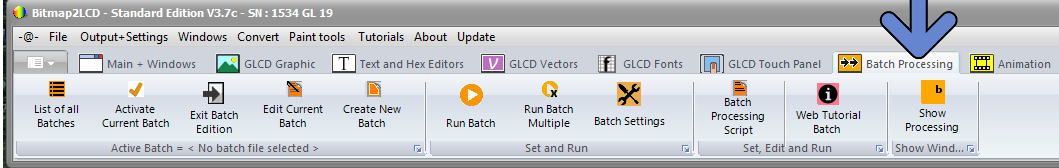
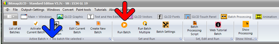
From Bitmap2LCD Version 3.0H

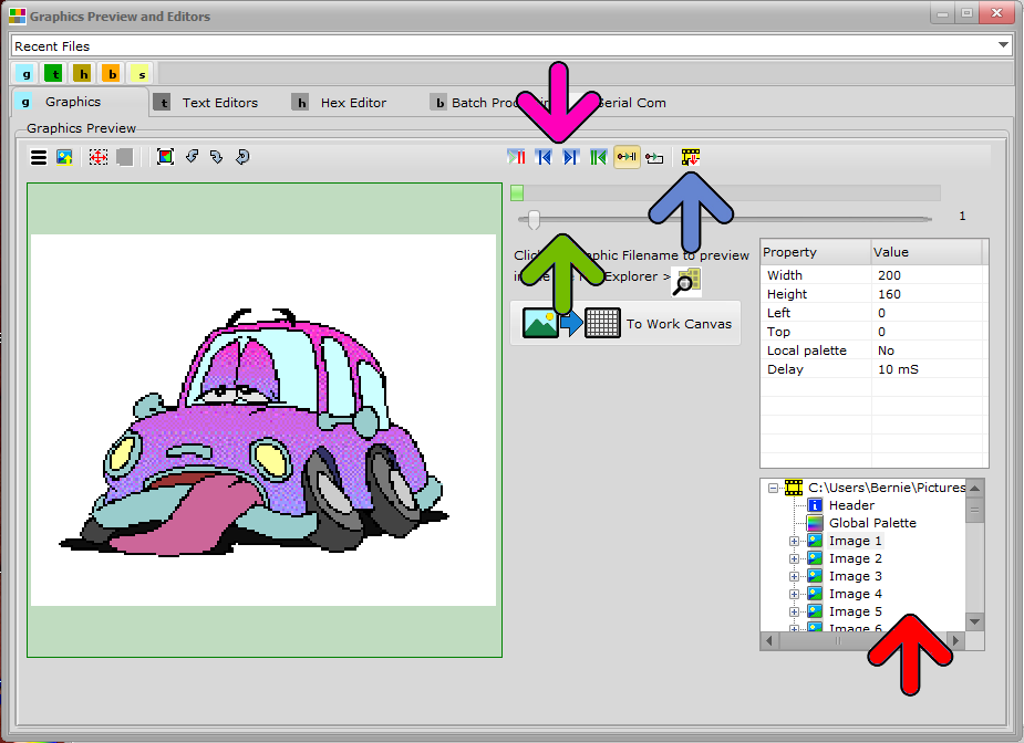
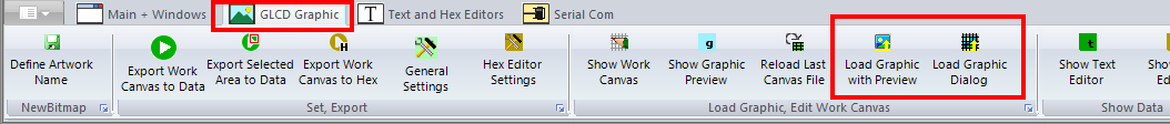
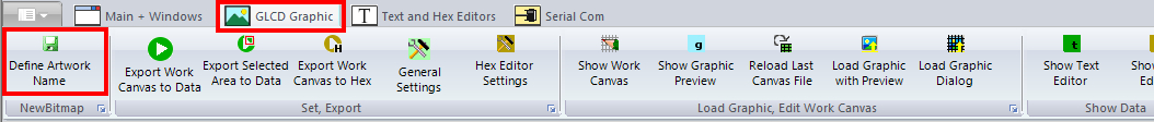
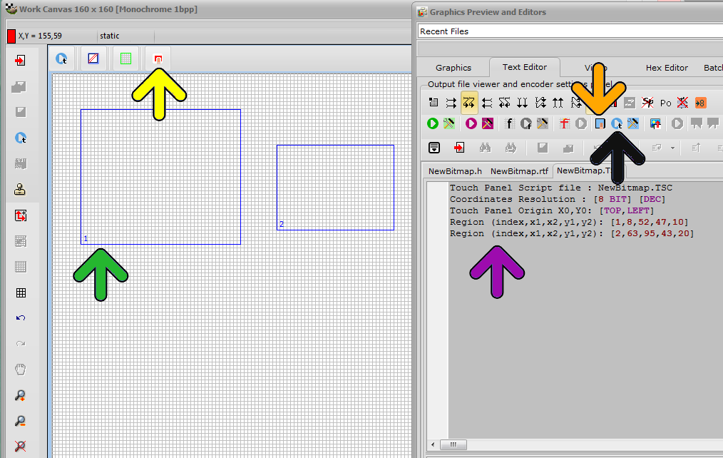
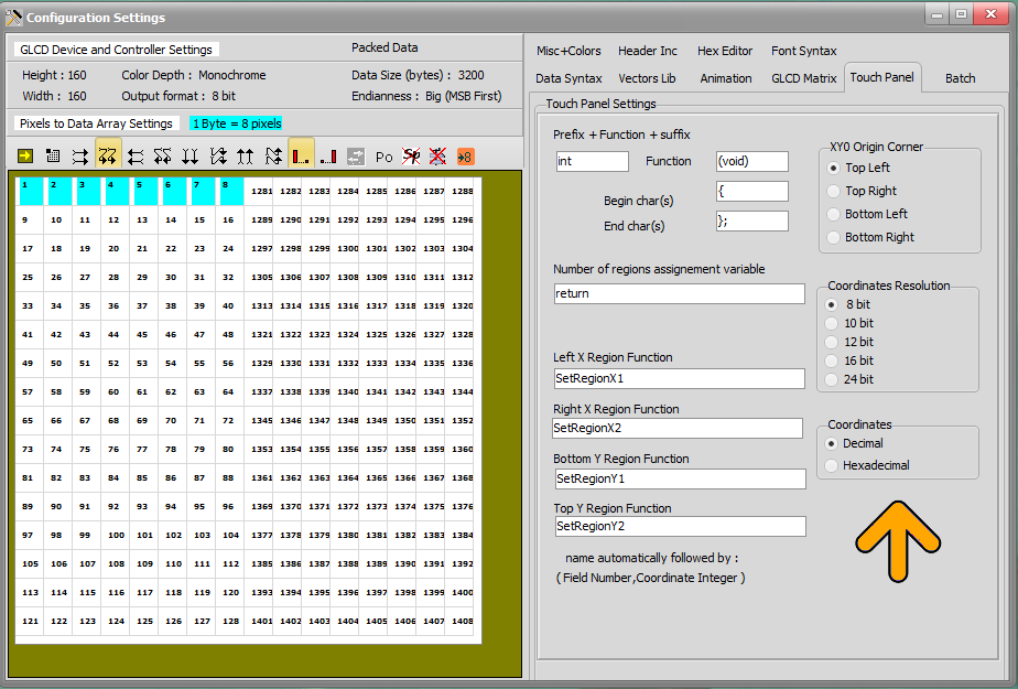
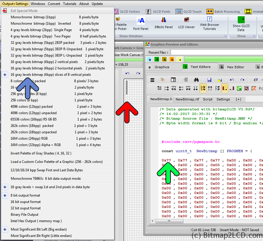
  • Enable the Special Mode (blue arrow) for ST7528 in the Output+Settings main menu
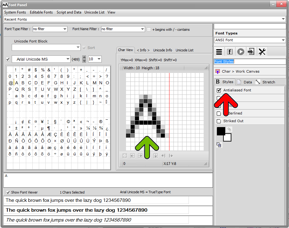
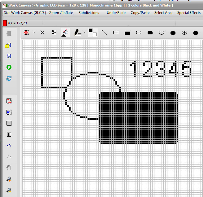
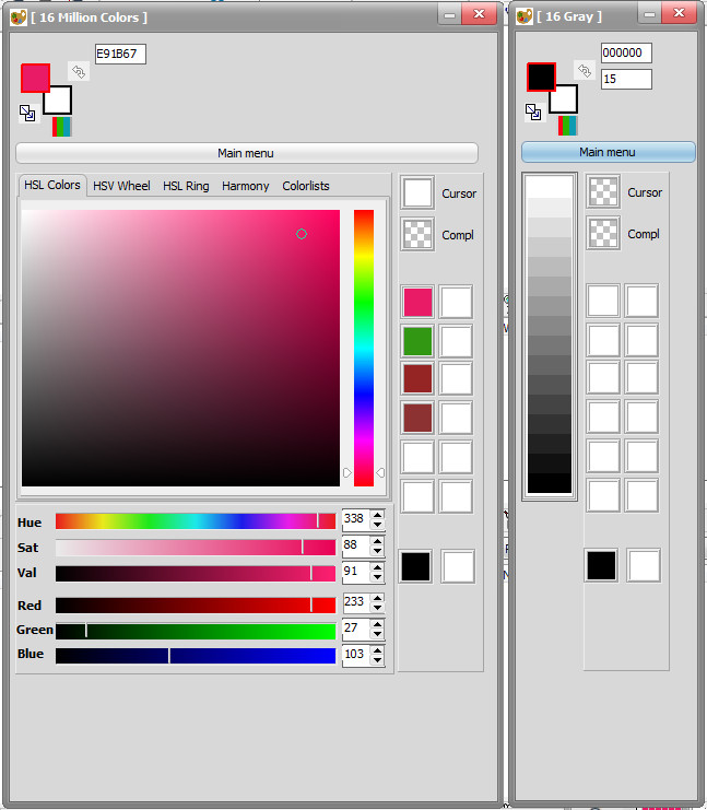
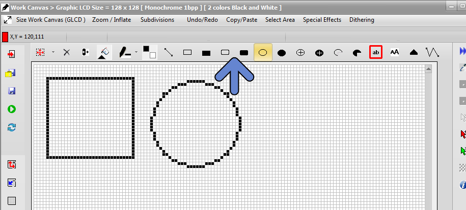
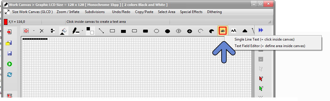
  • To check it out, just draw 8 pixels in height in the work canvas, in one of the gray colors to be found inside the color picker ( in this example the chosen color is 7 )  ( red arrow )
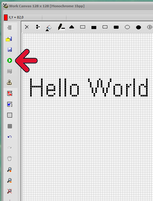
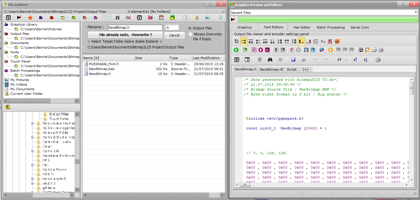
  • Export Work Canvas to data array 
  • Find your 8 pixels inside the data array, 4 x 0x77 , corresponding to the these 8 gray pixels ( green arrow )

When converting a picture into hex data for a graphic LCD of 160 x 100 pixels , you will get 8320 Bytes, in vertical slices of 8 pixels in height.  ( Normal Gray 4bpp Mode outputs slices of 2 pixels in height = 8000 bytes of data )

——-

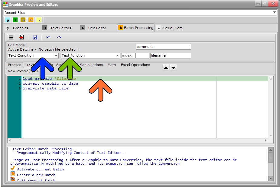
Before Bitmap2LCD Version 3.0H

Here’s the needed configuration of Bitmap2LCD for a data output for the ST7528 :

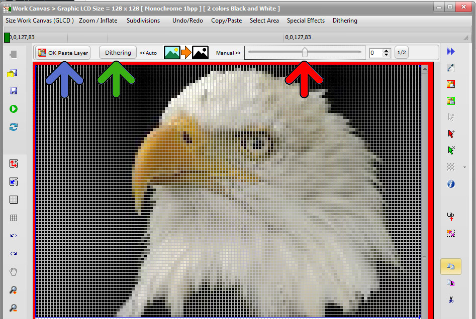
  • Enable the Special Mode (red Arrow) for ST7528 in the Output main menu
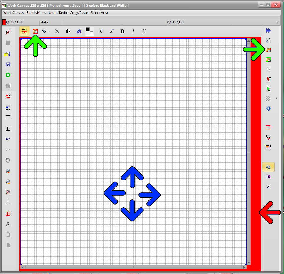
  • Select the correct data direction (blue arrow)
  • Enable the Special Mode ON/OFF Switch (green arrow)
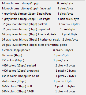
  • Select 4bpp Grayscale Mode in the Mode main menu

When converting a picture into hex data for a graphic LCD of 160 x 100 pixels , you will get 8320 Bytes, in vertical slices of 8 pixels in height.  ( Normal 4bpp Mode outputs slices of 2 pixels in height = 8000 bytes of data )

Other special Modes for the following Sitronix LCD controllers are planed in future upgrades :

4-Gray Graphic : ST7541 , St7571

32-gray Graphic : ST7529 , ST7586

Anti-Aliasing and Smoothing of GLCD images and fonts

Anti-Aliasing and Smoothing of GLCD images and fonts

Anti-aliasing or “font smoothing” is a process to make your images look smooth and your text more readable.

Anti-aliasing or font smoothing is a technique to make flat color images and text look smoother on grayscale GLCD screens. The font generator in the Bitmap2LCD tool features font smoothing for 16 grayscale OLED GLCD (4 bit pixel depth)
A graphic liquid crystal display shows an image in bitmap mode. It means that every image is really a bunch of tiny little squares that make up the image. In other words, fonts on monochrome GLCDs or monochrome fonts displayed on grayscale GLCDs, can’t display chars with smooth curves. With anti-aliasing, the curve is created with squares of color that are shaded darker or lighter depending on how much of the curve would take up that square. For instance, if a portion of a curve takes up 10% of a pixel, that pixel would be shaded with 10% of the color saturation of the curve, in fact in case of a 16 grayscale level GLCD, the nearest gray level of the 10%

Anti-aliasing Pros and Cons

Pros
  • Makes fonts look smoother
  • Rounded edges look round
  • Type is easier to read (for some) because it looks more like what printed type looks like
  • Some people feel it’s prettier

Cons

  • Small fonts become too fuzzy to read
  • Sharp edges may be fuzzy and not precise
  • You can’t print anti-aliased text as it comes out blurred
  • Images are generally larger
  • Type is easier to read (for some) because the blurring is reduced and the fonts are clear

Note : This post summarizes information found here and there on the web


Example of an Antialiased Character View in the Bitmap2LCD Font Panel

bitmap2lcd-antialiasing


Animations on Graphic LCD (GLCD)

Animations on Graphic LCD (GLCD)

With Bitmap2LCD, you can easily edit and play GLCD animations.

The goal is to create buttons with status dependent graphic effects, device power on and power off splash screens, animated logos, moving icons, display of analog gauges, creating impressive GLCD demos, symbolic displays of actions in progress or to show the current machine operation,  or an animated hourglass cursor to name a few.

One of the many interesting features of Bitmap2LCD is the support of GIF files.

To summarize , the GIF format supports up to 8 colors per pixel depth (max 256 colors) and also supports animations and allows a separate palette of 256 colors for each frame.

wikipedia about GIF

Here’s an example of a short animation made with Bitmap2LCD called HalfEmptyGlass.gif ( Monochrome, 28 frames )

Click on the image if you want to play the animation

The animation sequence is made of frames that you can handle inside Bitmap2LCD as single images.

There’s a built in animation sequence player , similar to a video player with Play/ Stop / pause /rewind /next frame / previous frame buttons.

When the animation is ready, you can export the animation in one run and click to a set of data arrays, with or without data compression, in case of a monochrome data output.

A GIF animation is a collection of images


Animation features of Bitmap2LCD

  • Import all frames of a GIF file inside the Work Canvas
  • Import a single frame of a GIF file as graphic
  • Import single images one by one into an animation and save it as a GIF
  • Create an animation from scratch
  • Remove, insert, add  frames in the animation
  • Play the animation sequence
  • Export animation to data arrays in one run


Import a GIF animation

When clicking inside the File Explorer file-explorer on the filename of a GIF file, You can 1) import a single frame from inside a GIF as a single graphic, or 2) import all of the frames of the animations inside the Work Canvas (GIF Import button -> blue arrow)

In the Graphics Preview Window, you can also play the animation (purple arrow) , find a specific frame using the track bar (green arrow) or browse the GIF using the GIF Components Browser (red arrow)

P57BU2H9V2FH

bitmap2lcd-glcd-animation_1

1) Graphic Preview ) GIF Import button -> blue arrow

bitmap2lcd-glcd-animation_2

2) Work Canvas ) Paste button -> green arrow

bitmap2lcd-glcd-animation_3

3) Work Canvas ) Edit Animation -> Yellow arrow -> Red frame

4) Start Export animation to data arrays

bitmap2lcd-glcd-animation_data_array_1

5) Text editors ) Browse data array files (blue arrow)

bitmap2lcd-glcd-animation_data_array_2

6) Text editors ) Check the clip unit 

( Filename format : clip_ArtWorkName_NumberOfFrames.h )

Text Processing Automation Tool

Bitmap2LCD is a tool for programming small Graphic LCDs in embedded systems and a programmable text processing tool.

Text Processing Automation Tool

( Function described here was updated from Bitmap2LCD V2.8a  , and is available with the Standard Edition license )

One of the various features included in the bitmap2LCD GLCD toolbox is the Source Code / Text file processing.

To find and replace text in many files or if it is needed to search and replace different data 100+ times at once, or to proceed to many other text processing tasks , the Bitmap2LCD tool will help you saving precious time to search and replace text in the blink of an eye.

You can program batch scripts of your repetitive text-processing tasks such as auto-replacement or/and auto-insertion of any text in your source code, save it to the disk (.SPP) and define it as the current active batch of a project.

The list of functions in the batch script makes it possible to search automatically for text strings within the code and based on the paired actions, decide whether the alternative text string shall overwrite the text string searched for, or be placed after it.

 Here’s the list of the functions available in the bitmap2LCD text processing tool

( Note : Addition of new functions in the future , also see blue arrow below in fig1. )

List of the conditions and modal switches

if ‘text’

if not ‘text’

while ‘text’

if line number(index)

if last line

if flag

if not flag

and ‘text’

and flag

and not ‘text’

and not flag

or ‘text’

or flag

or not ‘text’

or not flag

begin of loop

end of loop

search back from line end

search from line begin

case sensitive on

case sensitive off

..

List of the functions

then set flag

then reset flag

then insert (index)’text’

then overwrite (index)’text’

then remove ‘text’

then delete until ‘text’

then get integer (index)

then get hex (index)

then get float (index)

then insert integer (index)

then insert hex (index)

then insert float (index)

then next line

then delete line

then insert line

then save as ‘file’

then start copy

then stop copy

then start delete

then stop delete

then save copy as ‘file’

then load and insert ‘file’

etc..

To program a batch , click Edit Current Batch or click New batch ( buttons are located in the main menu )

bitmap2lcd-batch-processing-menu

bitmap2lcd-batch-processing_3

fig. 1

Then choose the conditional function in the Function combo box (blue arrow)

You can’t directly edit the text itself in the editor, but you can move the green cursor up and down in the program (orange arrow) and edit the index , text and comment fields of the line selected by the cursor, in the fields at the top of the editor (green arrow).

Note that the index field can be left at ‘index’ when the cursor position is not known nor fixed : Index is a numeric field , a cursor position of character or text or if left at ‘index’, it will be the cursor position where the searched ‘text’ was found in the conditional instruction before (‘if’) .

An IF followed by one or more THEN is a pass thru the whole text file loaded in the Text Editor (second tab fig1. ) Please remember that every IF + Then(s) Pair is a new pass from the top to the end of the text file.

In the above examples in fig1. and fig2 , a part of the file is copied in another file named copy3.txt located in the folder defined as output files folder .

bitmap2lcd-batch-processing-menu_2

fig 2.

The Processing batch can be started from the user interface, from a single button (see red arrow) or from a main menu item.

See also the article about the automatic post-processing in this topic.

How to use bitmap2LCD ? A Short Tutorial

Welcome to Bitmap2LCD  !

You can find various TUTORIALS on-line on the Bitmap2LCD BLOG.

https://bitmap2lcd.com/blog

The HELP topics are also easily accessible from inside the

 tool, using the internal Web Browser.


Presentation of Bitmap2LCD (Youtube)


Link for versions anterior to V3.7


Getting Started : A short tutorial

Bitmap2LCD is a software tool for programming small Graphic LCDs in embedded systems and a programmable text and graphic processing tool.


How to find information here ?

At the TOP RIGHT HAND SIDE of this BLOG you will find

For example the link (green arrow) of this Quick Tutorial
You also can search this website using keywords (orange arrow)

Bitmap2lcd Blog Search

and you can browse the listed topics

Translation of these Tutorials 

Translations  Traductions  Übersetzungen  Traducciones_ Traduzione 


Find Help and Tutorial using the Internal Web Browser

Use the Topic Menu Item as shown below


bitmap2lcd Web Browser

Fig 1 ) 

Already have discovered the presentation slide show on the website  ?

It’s the same sideshow as the one included in the demo/trial version of the software tool. A general info about what this is it all about.

Link to the Slideshow


The Windows

The red frame  below shows where, in the Main+Windows tab of the Main Menu, to open and show the different Windows of the Program

bitmap2lcd-windows

fig 2 )

Bitmap2LCD is a multi-window application and supports dual screen.

List of the windows : Main window, LCD Viewer, Configuration Settings, File explorer, Graphic and Editors Window, Tool menu, Work Canvas, Adjustments, Font Panel and internal Web Browser.

You can show or hide (minimize) the windows, move them to the secondary monitor.


.

.

Getting Started  > Basic Settings

GETTING STARTED > BASIC SETTINGS

.

.

The Work Canvas

It’s the GRAPHIC EDITOR, the paintbox , You can draw pixels and shapes, import graphics into it. It has a user defined “color depth” which is the same as the target GLCD of the project.

bitmap2lcd-work-canvas

Fig 3 )

The Color Depth of the Work Canvas

Monochrome , Grayscale or Colors

Bitmap2lcd Color depth

Fig 4 )

Details about the Work Canvas

Details about Grayscale


Load a graphic

LOADING A GRAPHIC USING A STANDARD WINDOWS DIALOG OR LOADING IT FIRST INTO PREVIEW ? 

  • You can either use the Load Graphic Dialog ( red frame )

bitmap2lcd-load-graphic

Fig 5 )

OR

  • open / switch to the FILE EXPLORER
  • In the list of files, click to select your particular graphic file you want to load (fig6 blue arrow) , it appears in the GRAPHICS PREVIEW window at the right side.
  • Resize or turn/tilt the preview image using the buttons located at the top of the GRAPHIC PREVIEW.
  • Double click in the graphics viewer (yellow arrow) or the click the import button located at the top or bottom of the preview (fig6. Green arrow)

bitmap2lcd-load-graphic-preview

fig 6). File explorer view

If the graphic is larger than the WORK CANVAS a message box will ask you if you want resize the image to fit the canvas or not.

The Floating Selection Layer

MOVING THE GRAPHIC IMPORTED INSIDE THE FLOATING SELECTION LAYER ? 

The graphic will be imported in the FLOATING SELECTION LAYER not directly into the WORK CANVAS (fig7. imagine your own graphic inside the canvas)

The red frame (fig7. red arrow) around the canvas means that you will have to PASTE paste the graphic into the canvas after MOVING it, convert it. When outline frame is red, it means that a “floating ” SELECTION LAYER above the canvas is displayed…

The imported graphic can be moved around above the Work canvas : Move/drag the red frame to the desired canvas location with the left mouse button pressed. (fig7. blue arrows)

Then PASTE paste the FLOATING SELECTION LAYER (fig7. green arrow) The red frame in the frame and around the work canvas disappears. (There are also other ways to Paste, in menus, using the return key etc..)

bitmap2lcd selection layer

fig 7 ) Import a graphic file

.

Converting a bitmap to Monochrome

THRESHOLD LEVEL OR DITHERING ?

If you’re loading a COLOR graphic file to convert to black and white for MONOCHROME GLCDs you have the choice of applying a Black and White THRESHOLD level (red arrow), or applying a DITHERING (green arrow) with monochrome color reduction.

Dithering Parameters are located in the main menu of this Window

When the conversion to Black and white is finished, PASTE the floating SELECTION LAYER (Blue Arrow) to the WORK CANVAS

Details about dithering

bitmap2lcd-convert-to-black-and-white-dithering

Fig 8 )

Converting a bitmap to GLCD data.

Start   Export WORK CANVAS Graphic To a DATA ARRAY inside the Text Editor

Start HEX   Export WORK CANVAS graphic to Data inside the HEX Editor / BINARY file

Start Selected Export a selected area of the WORK CANVAS To a Data Array inside the TEXT EDITOR

Bitmap2lcd export graphic

Fig 9 )

Start a Graphic To Data conversion (fig 9. red arrow)

Your hexadecimal file appears in the Text editor, formatted according to the defined configuration settings. (fig 10)

bitmap2lcd output file

Fig 10) Bitmap has been converted to the Hexadecimal, decimal or binary  file in the text editor.


Basic Configuration

Where to find and change the SETTINGS

Link to Basic Configuration

Example Of How to Convert A graphic To a Data Array

Example of how to convert a Graphic to a Array of Data

.

System font, Editable Font, Anti-aliased Font, GLCD Font  with Bitmap2LCD

Info about Fonts in Bitmap2LCD

.

Projects, Artworks and Filenames

A PROJECT is a set of configuration settings ( There are many possible settings ! )

If you work on different GLCD projects, you can save the “current” settings inside a Project name. It’s the easiest and fastest way to switch from one to another.

A so called “Artwork” is a set of files related to the graphic source filename : In the below example a graphic saved for example as NewBitmap.BMP , will be converted to an output file called NewBitmap.h , and the associated touch panel file will then be named NewBitmap.TSC (Red Arrow)  

When you save your Artwork with”Define Artwork Name”  in the GLCD Graphic Tab (Red Frames), as a bitmap,  you will change the basic filenames

bitmap2lcd-artwork-name

Fig 11 )

Color picker

Bitmap2LCD has built in functions which are very similar to the popular MS Paint program

You can select the foreground (PEN COLOR) and background colors (BRUSH COLOR) for painting and WRITING text by clicking in the color boxes of the menu window.

You can copy foreground color to background colors or swap them when clicking in the small boxes around the colors boxes.

bitmap2lcd Color PickerFig 12 ) The Color Picker ( Here the Color mode Picker and the 16 gray shades mode picker )


Drawing tools

Buttons are located At the top of the Work Canvas

bitmap2lcd-drwaing-toolsFig 13) drawing tools


Write a text

Button is located at the top of the Work Canvas (blue arrow)

bitmap2lcd-write-text

Fig 14 )

There are 2 different ways to write text inside the work canvas :

  • The Text Field Editor
  • The single Line Text editor

bitmap2lcd-write-text_2

Fig 15 )

Example of using the single Line Text Editor, text can be moved and pasted with paste


bitmap2lcd-field-text-editor

Fig 16 )

Example of using the Text Field Editor, text can be moved and pasted with paste


Working in Vector Mode (GLCD Library)

Using GLCD library functions like GLCD.rect(x,y,h,w) or GLCD.GotoXY(x,y) and similar :

Please follow this link :

Vector Mode

Target Code Example : Displaying a bitmap on an

Atmel AVR MCU

Code example

.

Software Updates

With Standard Edition of Bitmap2LCD, you get unlimited Software Updates

Details About Software Updates

Bitmap2LCD development and Support

A feature you would like to see implemented not yet available ?

submit us your Idea !  Need support  ? Contact us !


About the touch panel function in Bitmap2LCD

Bitmap2LCD is a tool for programming small Graphic LCDs in embedded systems.

Touch panel regions (green arrow) can be graphically defined in the work canvas.

  • If not already displayed, load the correct bitmap into the work canvas ( sample)
  • Create a Touch panel script (orange arrow)

The editor gutter becomes green = Touch Panel Script.

  • A region can be defined using the mouse with the area selection tool (green arrow)
  • When the touch panel region size and location are correct, convert the area to a region with the “Make touch region” button (yellow arrow)
  • When all regions where defined , convert the script to an output file (black arrow)

Note that you can edit, move, resize defined regions.

Bitmap2lcd Touch Screen Feature

Configuration settings for touch panel data output (see fig2)

  • In the Touch panel main menu (orange arrow) you can define the data direction and the Touch Screen controller resolution (8,10 or 12 bit)
  • In the toolTouch Configuration Settings Panel, under tab Touch Panel, you can define your favorite output syntax.
  • When converting the defined regions with the button (green arrow) the data in the editor then contains the regions, with field number and the 4 coordinates of each region.

Bitmap2lcd Touch Screen Settings

Start touch Then convert the Touch Panel Regions to Data :

Bitmap2lcd Touch Screen Data


About the File Explorer in Bitmap2LCD

Bitmap2LCD is a tool for programming small Graphic LCDs in embedded systems.

File explorer files view settings

  • include / exclude the folders in/from the list of files ( yellow arrow )
  • include / exclude older than today’s files in/from  the list of files ( blue arrow )
  • Refreshing the list of files, for example after insertion of a USB Stick
  • Filtering the list to only show a family of files. ( fig1. the file filter list is popped up )

If any file list filter is set, in the status bar at the top right side of the file explorer, the count of elements is displayed as NOT FILTERED OUT.

Use the file explorer’s project path in Bitmap2LCD

Bitmap2LCD is a tool for programming small Graphic LCDs in embedded systems.

At the top left side of the file explorer, you can set your 5 different project folders.

You can differentiate Graphic files, Output files ,Documentation files, Fonts files and Touch Panel files.

When you’ve selected the folder in the file explorer, click the blue, red, yellow, green or orange icon (fig1. blue arrow at the bottom)  corresponding to the files family, in order to set the path.

Later on, you can either click on one of the the direct links (red arrow) for unfiltered files lists or on the file family (for example upper blue arrow) to display a filtered list. (This files filtering option can be disabled or enabled at the bottom of the filters menu)


New window layouts and menus ( since Bitmap2LCD v2.0 )

Bitmap2LCD is a tool for programming small Graphic LCDs in embedded systems.

From v2.0 upwards, the work canvas window ( pixel painting grid ) became smaller than before and the former large menu at the top of the main window, has been replaced by a main menu (blue arrow) and sub-menu (red arrow ) structure. Sub-menu content just changes depending on what’s selected on Main menu.

A new fast access menu is accessible by right-clicking at the down right corner work canvas button or on the horizontal and vertical scrollbars. (Green arrows)

When the Work Canvas Window background is red, it means that an active area selection is still active ! This area can be moved by a mouse drag, and then pasted at the right position.

The pixel color can be selected by right- ( or left-) clicking on the foreground/background color icons (On the fig. below black=FG White =BG).

Foreground and background colors, can also easily be swapped.

Grayscale GLCD >> 16 gray levels basics

Bitmap2LCD is a universal programming tool for converting bitmaps/images to GLCD for most graphic LCD controllers.

This software tool can be used for programming embedded systems connected to a Grayscale Small Graphic LCD ( OLED ) with a built-in COG LCD controller similar to the ST7528.

For a start, here’s a short article about 4bpp grayscale (4-bits per pixel ) for displaying 16 levels of gray.

The values from 0  through 15 decimal (00 to 0F hex) correspond to lightest (white) through darkest (black) as shown in the representation below.

A single byte in the DDRAM can be used to store 2 pixels of information.

When using a module with an on glass ST7528 LCD controller, in the source code data byte, the first pixel data comes after the second pixel data :  22221111

With bitmap2LCD [from v2.0 upwards] you can set ON the automatic pixel data nibble swapping, for a correct ordering in the source code output.