Tag Archives: LCD controller

About the Toshiba T6963C LCD Controller

About the Toshiba T6963C LCD Controller

The Toshiba T6963C graphics controller chip is designed to control small to medium size graphic Liquid Crystal Display modules (LCD). It may be interfaced with a number of different 8-bit micro-processor units (MPU) such as the Z-80 or the 80C51/80C52.

It provides the necessary interface between the MPU and the video RAM (VRAM). It also generates the necessary timing and data signals for the liquid crystal driver circuits. It has a 128 character Character-Generator ROM (CG-ROM) and has the capability to control upto 64K bytes of external display RAM (VRAM). This VRAM may be allocated for text, graphics and external character-generator RAM (i.e. a user definable character generator). The T6963C can support a wide variety of LCD formats and has the ability to combine text and graphics data on to the LCD. A number of character attribute functions are also available.

Main Functions and Features of T6963C

– Simple 8-bit parallel interface
– Hardware Selectable Display Formats: Columns: 32, 40, 64, 80 – Lines: 2, 4, 6, . . . . . 28, 32
– Hardware Selectable Fonts(W) x (H): 5×8, 6×8, 7×8, or 8×8
– Programmable Duty Cycles: 1/16 to 1/128
– Internal 128 character CG-ROM
– Software allocation of Text, Graphic and Character Generator RAM (CG-RAM)
– Ability to mix and merge text with graphics
– Low power CMOS design
– Operates up to 5 MHz

The Aslic AX6963 , The RAIO RA6963 are T6963 compatible LCD controller devices

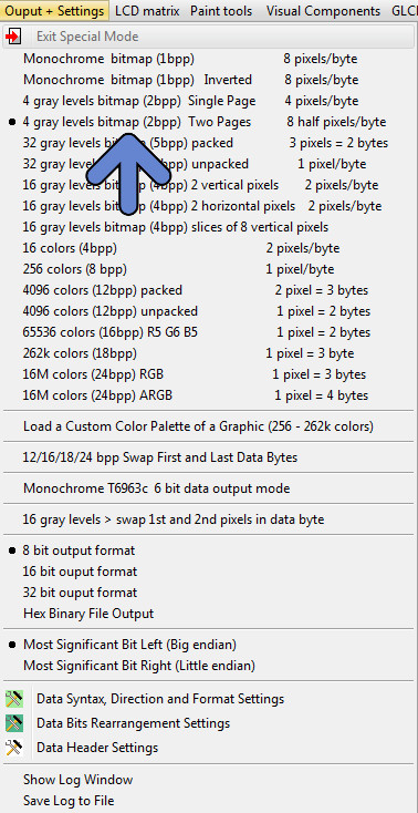
Bitmap2LCD supports the T6963c 6 bit display mode

Generating 2bpp grayscale data on two pages

Bitmap2LCD is a tool for programming small Graphic LCDs in embedded systems and a programmable graphic and text processing tool.

Generating 2bpp grayscale data on two pages

From Version 3.4b, a new setting for an alternative output format for 2bpp grayscale has been implemented.

The data then is generated in two separate data arrays (or pages) : The first page of 1bpp data is to turn on light gray, and the second page of 1bpp data is to turn dark gray.

For example, for a 128 x 96 2bpp gray LCD Panel, the generated data is split in two arrays of 128 x 12 bytes. Each byte contains 1bpp of 8 pixels, combined with the other byte in the other array to make the 2bpp.

Target : For example LCD controller S6B0741 (Samsung)

bitmap2lcd 4bpp grayscale

Grayscale GLCD >> 16 gray levels basics

Bitmap2LCD is a universal programming tool for converting bitmaps/images to GLCD for most graphic LCD controllers.

This software tool can be used for programming embedded systems connected to a Grayscale Small Graphic LCD ( OLED ) with a built-in COG LCD controller similar to the ST7528.

For a start, here’s a short article about 4bpp grayscale (4-bits per pixel ) for displaying 16 levels of gray.

The values from 0  through 15 decimal (00 to 0F hex) correspond to lightest (white) through darkest (black) as shown in the representation below.

A single byte in the DDRAM can be used to store 2 pixels of information.

When using a module with an on glass ST7528 LCD controller, in the source code data byte, the first pixel data comes after the second pixel data :  22221111

With bitmap2LCD [from v2.0 upwards] you can set ON the automatic pixel data nibble swapping, for a correct ordering in the source code output.


Bitmap to GLCD Hex file >> Output settings

Bitmap2LCD is a tool for programming small Graphic LCDs in embedded systems.

Go to the Main Settings (v2.5 +):

bitmap2lcd settings

From V2.5, the below settings can also be found on the file explorer window, outputs tab : there’s a button at the top right to hide or show this toolbar.


fig 1. Hex file output settings buttons [ Bitmap2LCD from V2.0 upwards ]


Bitmap2LCD is a universal programming tool for converting bitmaps/images to GLCD for most graphic LCD controllers. (Monochrome,Grayscale, and Color ->[Color from V2.0] )

The software converts the bitmap and generates a hexadecimal file according to the previously defined user settings.

Here’s a short description of the available settings :

The hexadecimal output format can be selected with a series of buttons located in the output panel (fig 1.)

Description of the settings:

  • The choice of 8 different vertical or horizontal pagings ( the buttons with the arrows ) , your choice depends of the GLCD controller which is built in your LCD module. ( Please refer to the GLCD controller datasheet )
  • Most significant bit is first or is last (Data bit 7) — or in other words the data endianness.
  • Byte nibble swap On/Off, for example for 16 gray level grayscale mode for Sitronix ST7528 controller compatibility. ( In the case of 2 pixel per data byte, 4 bit per pixel data, gray levels )
  • Negative or positive output setting
  • GLCD zero corner selection (Corner where the conversion starts)
  • Output File Header Editor , (A small script to configure Hex file header)
  • Enable/Disable of the Output Data for compression for monochrome GLCD.
  • Enable/Disable 6 or 8 bit Data byte wide output for T693C Controller

As the converted output can just contain a part of the display size, there are other selectable options (not on fig1.)

  • Enable/disable X,Y area coordinate data insertion in the Hex ouptut file
  • Enable/disable area size data insertion in the Hex output file

These configuration settings are saved when you quit the application and restored on application launch. These settings are also a part of the project specific configuration.

Find other available settings in this topic.


Color GLCD Displays

In color GLCDs, each individual pixel is divided into three cells, or subpixels, which are colored red (R), green (G), and blue (B).

In GLCDs, the most important thing in interfacing color GLCD is to know how color is defined to a given pixel. Available formats depends on the brand and type of GLCD controller built in the choosen module :

12 bit per pixel pixel format (12bpp)
RRRRGGGG  4 bits red and 4 bits green 1st pixel BBBBRRRR   4 bits blue 1st pixel and 4 bits red 2nd  pixel GGGGBBBB  4 bits  green and 4 bits blue 2nd pixel

8 bit per pixel pixel format (8bpp)
RRRGGGBB  3 bits red, 3 bits green and 2 bits blue

16 bit per pixel pixel format (16bpp)
RRRRRGGG  5 bits red and 3 bits green 1st pixel GGGBBBBB  3 bits red and 5 bits blue 1st pixel

The Bitmap2LCD programming tool supports these GLCD color formats from V2.0.