Bitmap2LCD is a tool for programming small Graphic LCDs in embedded systems and a programmable graphic and text processing tool.
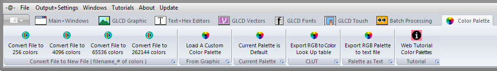
Export RGB Color Palettes to Text File or to a Look up Table [LUT]
From V3.8e , the above function has been moved to the COLOR PALETTE tab , Main Menu
( From V3.2e Build 4 to V3.8d )
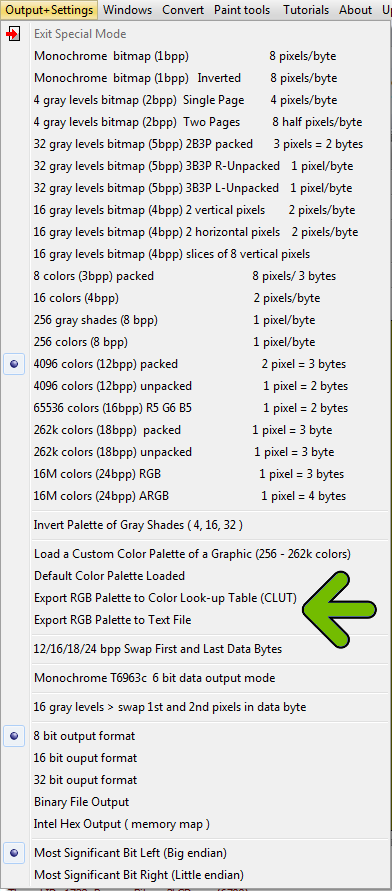
In the Output + Settings main menu, in the 256, 4096, 65536 and 262k Colors mode you can export the default or custom Color Palette to a text file. ( RGB 24bit Color Hex codes )
The exported file will be saved in the project output files folder
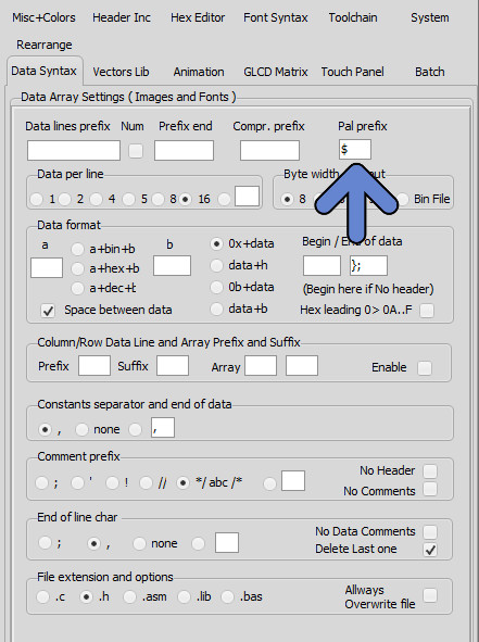
The prefix of the RGB 24bit Color Hex codes can be defined in the settings ( data Syntax Tab )
Bitmap2LCD is a tool for programming small Graphic LCDs in embedded systems.
Bitmap2LCD V2.1b and upwards supports the Sitronix ST7528 grayscale GLCD
The Sitronix ST7528 is a 16-Grey Scale Dot Matrix LCD Controller/Driver
< Quote >
The ST7528 LCD controller does not address rows directly, but rather groups of 8 rows in pages. The LCD memory on the controller is organized into 13 8-bit pages and 160 four-bit column addresses.
There are commands to set the starting page address and column address for a write operation, but no commands to select a row address – you must determine what page the row you want to write is in and set the page address that includes that row. This also implies that if you want to write pixels on adjacent pages, you must address the first page and column(s), write the data, then increment the page address to write the pixels in the adjacent page.
The controller also happens to use what seems like a very bizarre way to load pixel data. Logically, once the address is set, you would write the 4-bit pixel data (or maybe write 2 pixels at a time with a single byte). However, since the addressing scheme addresses pages and not rows, this approach is not used.
Instead, one bit of data for the entire addressed column of pixels (8 vertical pixels) in the current page is written with each byte sent to the LCD. Since each pixel requires 4 bits of data to define the grayscale level, 4 bytes of data must be sent per column to fully define the bits. While this data is being clocked in, the “main” column address does not change. Only after the fourth bit is written to a column is the main column address pointer automatically incremented inside the LCD controller so the next 4 bytes of data sent to the LCD will write the bit data for the next column.
To be complete, we must comment that the “column address” that you send to the LCD controller is actually bits 9:2 of a larger column address inside the controller. The bottom two bits 1:0 are “internal column” address bits. When the 4 bytes of data are written to the LCD controller by the MCU, the internal column address bits increment after each byte write. After the fourth byte is sent, the internal bits will roll from b’11’ to b’00’ and subsequently increase bit 2 of the column address. As you can probably guess, if you do not write LCD data to the controller in groups of 4 bytes, than you will not have complete data for the pixels and the internal LCD addressing will be corrupt.
The implication of all this is that you cannot ever write a single pixel on this LCD. The smallest number of pixels that can be refreshed is a 1 column x 8 row line and it will always take a minimum of four bytes sent to the LCD controller from the MCU to properly set those pixels. If you really do only want to update one pixel in the 1×8 column, you must be sure to write the same data that is already present for the other 7 pixels so their information does not change. This is where keeping a local copy of all pixel data in the LCD RAM becomes essential as individual pixels can be changed in the local RAM as the application requires it, and pixel data for unchanged pixels will still be present for the LCD refresh…
< End of Quote >
Quote from this well written Application Note : ST7528 Appnote
From Bitmap2LCD Version 3.0H
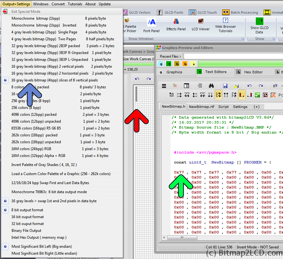
Enable the Special Mode (blue arrow) for ST7528 in the Output+Settings main menu
To check it out, just draw 8 pixels in height in the work canvas, in one of the gray colors to be found inside the color picker ( in this example the chosen color is 7 ) ( red arrow )
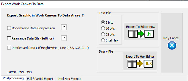
Export Work Canvas to data array
Find your 8 pixels inside the data array, 4 x 0x77 , corresponding to the these 8 gray pixels ( green arrow )
When converting a picture into hex data for a graphic LCD of 160 x 100 pixels , you will get 8320 Bytes, in vertical slices of 8 pixels in height. ( Normal Gray 4bpp Mode outputs slices of 2 pixels in height = 8000 bytes of data )
——-
Before Bitmap2LCD Version 3.0H
Here’s the needed configuration of Bitmap2LCD for a data output for the ST7528 :
Enable the Special Mode (red Arrow) for ST7528 in the Output main menu
Select the correct data direction (blue arrow)
Enable the Special Mode ON/OFF Switch (green arrow)
Select 4bpp Grayscale Mode in the Mode main menu
When converting a picture into hex data for a graphic LCD of 160 x 100 pixels , you will get 8320 Bytes, in vertical slices of 8 pixels in height. ( Normal 4bpp Mode outputs slices of 2 pixels in height = 8000 bytes of data )
Other special Modes for the following Sitronix LCD controllers are planed in future upgrades :
Bitmap2LCD is a tool for programming small Graphic LCDs in embedded systems.
Update V3.9H
A simple data compression feature, for the output of GLCD data arrays is implemented in Bitmap2LCD
This function is only available for monochrome mode and 8 bit output format.
The 8 bit microcontrollers for price sensitive projects are circuits with often less onchip memory space than most of the 16 or 32 bit devices.
The target is to save as many as microcontroller flash memory as possible. As tables for full display patterns of for example a 128 x 64 dot matrix LCD need 1024 bytes each, the goal of this function was to save flash space for more code or graphics or just to reduce the overall flash capacity and therefore to sink the price of the MCU chip.
The microcontroller firmware has to be able to handle these tables with a special code, which decodes the compressed data. Processing time for decompression has to be allowed.
How does it work ?
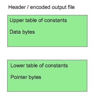
Instead of only converting the black and white pixels found in the work canvas to a linear list of n bytes, with the data compression method explained here, the data array is split into two separate arrays in one single output file : one as usual for the data stream and another for the pointers of each data groups.
The basic concept of this compression is based on making groups of consecutive identical data bytes in the data array.
Consecutive identical byte chains, and consecutive different byte chains are handled, the goal here is to save data bytes when a consecutive identical byte chain is found. While the first pointer of a consecutive different bytes chain is a loss of one data byte stored as a pointer, a consecutive identical byte chain of 10 bytes is a win of 8 bytes, the data being written only once in the data array. The count of them is then stored in the pointer byte array part.
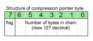
The maximum count of consecutive data, identical or different is limited to 127 ( pointer bits 6 to 0 ). If a data count in a group reaches 127, a new group is encoded.
The bit 7 of the pointer byte is the flag for the compression decoder. A 1 (high) is for a chain of identical data bytes, and a 0 (low) is for an chain of different data.
When data compression is active, Bitmap2LCD converts all data and shows the compression rate in the compression statistics at the end of the output file.
This method of compression shows different results in vertical or horizontal orientation conversion, it depends of the LCD graphic !
If possible, before to choose the LCD controller and its specific data orientation in Display RAM , you could try both orientations and compare the possible compression ratios.
In the Header Include file, the example script below shows how to setup the compression table information.
( It is an example for a GNU-C compiler for ATMEL AVR family )
Everything after the tag [&COMPRESSION] is a script information for the data compression function.
The tag [&CNAME] is replaced in the output table name, by the data array name
with an additional suffix _x ( For example : Newfile_x )
Alphanumeric (character) LCD module vs Graphic LCD Module
Comparing Font :
A large number of alphanumeric LCD modules are based on the Hitachi HD44780 which contains a character generator.
All the Character LCD controllers have their own fixed font and character generator. (CGROM)
Many of the newer Graphic LCD controllers have their own internal font. So you can send it as text, and it will draw it for you. (For example the good old T6963C is having an internal CGROM) Others do not, in which case you will need to send a bitmap of the character to the display.
The size of the library code that drives the actual device is obviously larger for the Graphics chip, and an external font uses program memory.
If you are tight for memory space then choose the type with an internal font and smallest library.
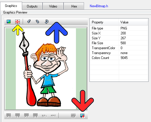
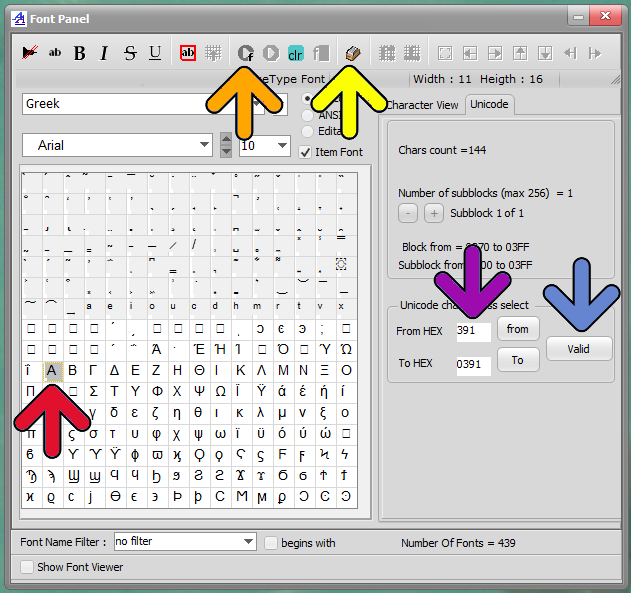
Since v2.6B, there’s a new toolbar at the top of the graphic (blue arrow)
When importing a graphic file, you can choose to resize the graphic size in the graphic preview (yellow arrow) or turn the graphic or reload the original graphic.
If the graphic is much larger in size than the work canvas, you will see a “blue frame” in the preview, frame which shows the size of the Work Canvas. You can move this area to the graphic detail you wish to import. In this case, the later message box resize to fit should be answered with NO.
When you want to resize the graphic, click on the selection button (yellow button) and then define the size on the image with mouse. The preview will be resized.
When ready import the graphic (red arrow) to the floating selection layer above the work canvas. When ready paste the floating selection layer.
Bitmap2LCD is a tool for programming small Graphic LCDs in embedded systems.
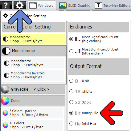
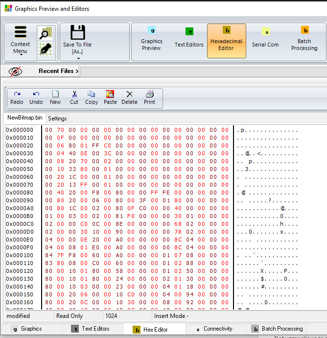
Output of the GLCD data array in a binary file
The converter data output feeds a built in hexadecimal editor and is saved to disk in a binary file (*.hex)
Output of the GLCD data array in a INTEL Hex format
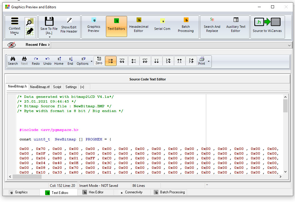
Output of the GLCD data array in a text file for the compiler or assembler, format 8, 16 or 32 bit data
The converter data output feeds a built in text editor and can saved to disk in a text file
( *.c , *.h , *.asm , “.lib etc..)
Next to the data file, a rich text file (*.rtf) which contains all GLCD conversion parameters is written to disk, in the user defined “Documents folder”.
Bitmap2LCD is a tool for programming small Graphic LCDs in embedded systems.
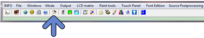
From v2.0 upwards, the work canvas window ( pixel painting grid ) became smaller than before and the former large menu at the top of the main window, has been replaced by a main menu (blue arrow) and sub-menu (red arrow ) structure. Sub-menu content just changes depending on what’s selected on Main menu.
A new fast access menu is accessible by right-clicking at the down right corner work canvas button or on the horizontal and vertical scrollbars. (Green arrows)
When the Work Canvas Window background is red, it means that an active area selection is still active ! This area can be moved by a mouse drag, and then pasted at the right position.
The pixel color can be selected by right- ( or left-) clicking on the foreground/background color icons (On the fig. below black=FG White =BG).
Foreground and background colors, can also easily be swapped.
Bitmap2LCD is a tool for programming small Graphic LCDs in embedded systems.
Go to the Main Settings (v2.5 +):
From V2.5, the below settings can also be found on the file explorer window, outputs tab : there’s a button at the top right to hide or show this toolbar.
Bitmap2LCD is a universal programming tool for converting bitmaps/images to GLCD for most graphic LCD controllers. (Monochrome,Grayscale, and Color ->[Color from V2.0] )
The software converts the bitmap and generates a hexadecimal file according to the previously defined user settings.
Here’s a short description of the available settings :
The hexadecimal output format can be selected with a series of buttons located in the output panel (fig 1.)
Description of the settings:
The choice of 8 different vertical or horizontal pagings ( the buttons with the arrows ) , your choice depends of the GLCD controller which is built in your LCD module. ( Please refer to the GLCD controller datasheet )
Most significant bit is first or is last (Data bit 7) — or in other words the data endianness.
Byte nibble swap On/Off, for example for 16 gray level grayscale mode for Sitronix ST7528 controller compatibility. ( In the case of 2 pixel per data byte, 4 bit per pixel data, gray levels )
Negative or positive output setting
GLCD zero corner selection (Corner where the conversion starts)
Output File Header Editor , (A small script to configure Hex file header)
Enable/Disable of the Output Data for compression for monochrome GLCD.
Enable/Disable 6 or 8 bit Data byte wide output for T693C Controller
As the converted output can just contain a part of the display size, there are other selectable options (not on fig1.)
Enable/disable X,Y area coordinate data insertion in the Hex ouptut file
Enable/disable area size data insertion in the Hex output file
These configuration settings are saved when you quit the application and restored on application launch. These settings are also a part of the project specific configuration.