Tag Archives: convert graphic

Export a Graphic to a GLCD Data Array

Bitmap2LCD is a tool for programming small Graphic LCDs in embedded systems and a programmable graphic and text processing tool.

Export a Graphic to a GLCD Data Array

Update V4.6c

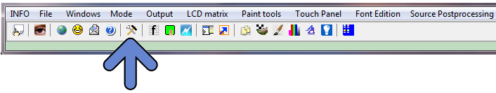
1. Open the File Explorer Window

2. If needed, select the Graphics Project Folder

3. Select the Graphic Filename

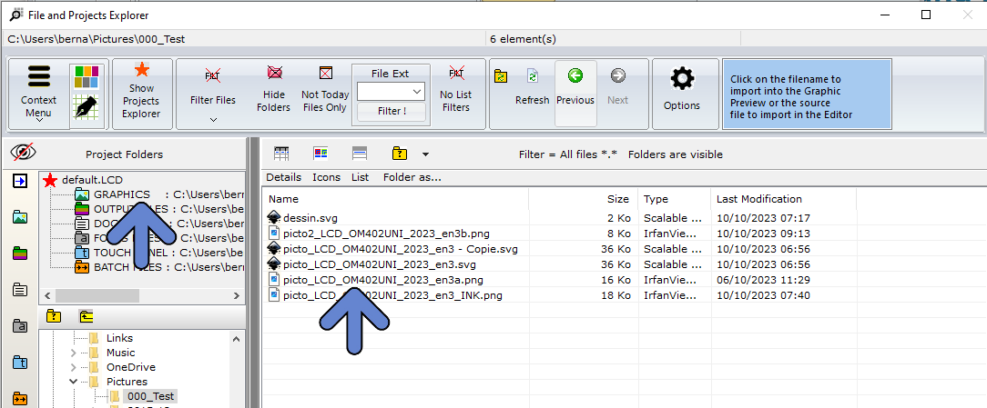
4. Graphic is opened in the Graphics Preview Window

5. If needed, adjust options like size, color reduction and orientation.

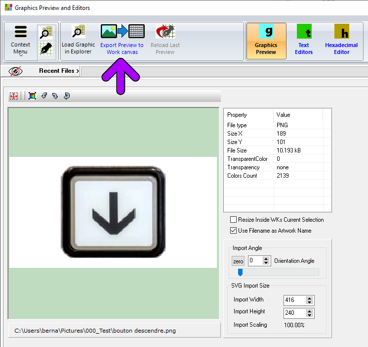
6. Export Preview to the Work Canvas( purple arrow )

7. Graphic is inside the FLOATING SELECTION LAYER, above the Work Canvas surrounded by a red frame

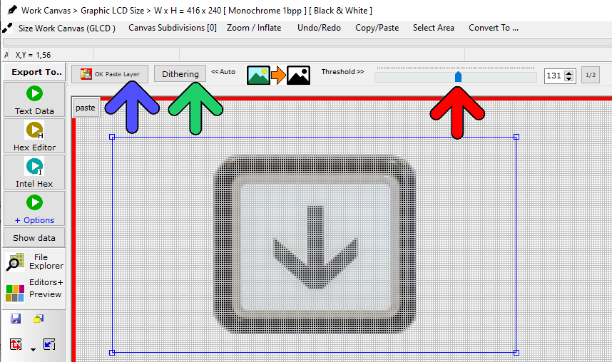
8. In this example, a conversion to monochrome is required. (monochrome GLCD)

9. Either choose Black and White THRESHOLD LEVEL with Adjustment Slider conversion or one of the DITHERING ALGORITHMS, like for example Floyd Steinberg.

10. If needed, drag the FLOATING SELECTION LAYER to its destination position on the canvas.

11. PASTE the selection layer to the WORK CANVAS ( blue arrow )

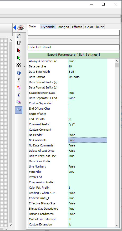
12. If needed, adjust the export parameters in the green column, Data Tab

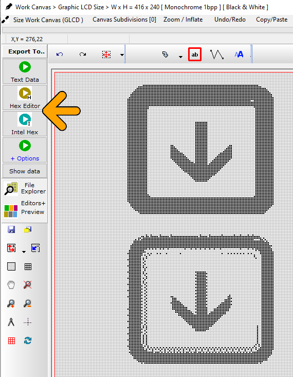
12. Export the Work Canvas to data array (Choose one of the Export Options : orange arrow)

13. Job done !

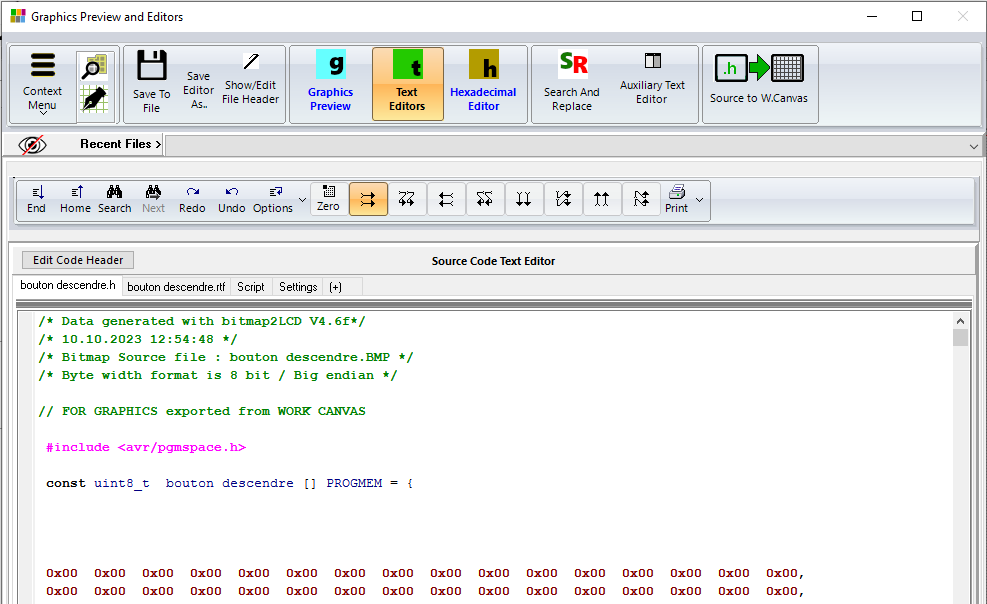
Note : With the 8 buttons with arrows at the top of the source code editor, adjust the data direction to match the display memory of the GLCD controller.

Bitmap2LCD : Graphic Processing Functions

Bitmap2LCD is a tool for programming small Graphic LCDs in embedded systems and a programmable graphic and text processing tool.

From Bitmap2LCD V2.9 and upwards , article update V3.6h

Bitmap2LCD : Graphic Processing Functions

Note : Additional Processing functions will be implemented in the future


load graphic ‘filename’           

Loads the defined graphic defined under filename in the Graphics Library Folder into the Work Canvas, converts the graphic to the configured graphic mode. ( grayscale,color ) No directory allowed under ‘filename‘ !

For multiple graphic file processing , there must not be a filename defined :  ‘filename’

convert graphic to hex

Converts the work Canvas to a Data Array inside the Text Editor

overwrite text file

Saves or Overwrites (without prompt if already exists) the text file with the text Editor Content. Filename is the same as the graphic source file name with configured data file extension, and is saved in the defined output files folder.

For multiple file processing , the output files are saved in a subdirectory of the graphic files source folder


GLCD Data Output Settings in Bitmap2LCD

Bitmap2LCD is a tool for programming small Graphic LCDs in embedded systems.

This article is only for releases before V2.5

Let’s look how to configure the GLCD data output settings :

The generated data array file (orange arrow, in the picture below) can be configured to meet the syntax requests of your compiler or assembler. There are many possible settings, to make it possible to match the tool with most of the compilers of the market.

At first, you define the table data settings (red arrow)

  • Data Width format. ( 8,16 or 32 bits data)
  • Binary, Hex or decimal format.
  • Syntax of Data Byte/Word (make it compatible with your favorite compiler, assembler)
  • Type of file (extension)

As next, you define the header syntax (green arrow)

  • Click on the button and the header script is loaded into the editor. Modify it to meet your requirements.
  • When ready, quit the header editor by clicking the same button (green arrow at the right) or the quit button. (script is auto-saved)
  • Find more about the header syntax at the end of this article.


As next, you define the way the data arrays are arranged to correctly fit in the DDRAM of your LCD controller. These settings must be compatible with the LCD display functions in the GLCD Library you use in your project (blue arrow)

  • The origin corner X0,Y0
  • Data direction (The direction in which the pixels slices are taken from the work canvas and converted to GLCD data, for example in slices or in full canvas height or full canvas width. A slice is 8 pixels in monochrome mode and 2 pixels in 4bpp grayscale mode)
  • The Endianness (Most Significant Bit is first or last)
  • Special settings


More about File Header syntax (green arrow)

The script components [&***] can be included only once and will be replaced by the data or value when the data array is generated. Not needed script components can be erased.

[&NAME]

The [$NAME] and the image size and position are optional and can be placed optionally anywhere in the header.

[&SIZE]

Same for Size of Data

[&TRUEORG]

This is the script component if present in the file, to indicate that you want to have the XPOS and YPOS origins of a reduced dynamic table of constants ( a part of the display you want to change ) given from the X0,Y0 corner you selected in the table translation manager window.

[&XPOS]

[&YPOS]

[&WIDTH]

[&HEIGHT]

The corner position on the Work Canvas and the size of the converted graphic area can be exported into the file.

There are additional script components for font generation and data compression.


Bitmap to GLCD Hex file >> Output settings

Bitmap2LCD is a tool for programming small Graphic LCDs in embedded systems.

Go to the Main Settings (v2.5 +):

bitmap2lcd settings

From V2.5, the below settings can also be found on the file explorer window, outputs tab : there’s a button at the top right to hide or show this toolbar.


fig 1. Hex file output settings buttons [ Bitmap2LCD from V2.0 upwards ]


Bitmap2LCD is a universal programming tool for converting bitmaps/images to GLCD for most graphic LCD controllers. (Monochrome,Grayscale, and Color ->[Color from V2.0] )

The software converts the bitmap and generates a hexadecimal file according to the previously defined user settings.

Here’s a short description of the available settings :

The hexadecimal output format can be selected with a series of buttons located in the output panel (fig 1.)

Description of the settings:

  • The choice of 8 different vertical or horizontal pagings ( the buttons with the arrows ) , your choice depends of the GLCD controller which is built in your LCD module. ( Please refer to the GLCD controller datasheet )
  • Most significant bit is first or is last (Data bit 7) — or in other words the data endianness.
  • Byte nibble swap On/Off, for example for 16 gray level grayscale mode for Sitronix ST7528 controller compatibility. ( In the case of 2 pixel per data byte, 4 bit per pixel data, gray levels )
  • Negative or positive output setting
  • GLCD zero corner selection (Corner where the conversion starts)
  • Output File Header Editor , (A small script to configure Hex file header)
  • Enable/Disable of the Output Data for compression for monochrome GLCD.
  • Enable/Disable 6 or 8 bit Data byte wide output for T693C Controller

As the converted output can just contain a part of the display size, there are other selectable options (not on fig1.)

  • Enable/disable X,Y area coordinate data insertion in the Hex ouptut file
  • Enable/disable area size data insertion in the Hex output file

These configuration settings are saved when you quit the application and restored on application launch. These settings are also a part of the project specific configuration.

Find other available settings in this topic.