Warning: Constant FORCE_SSL_ADMIN already defined in /home/wservicezi/www/bitmap2lcd/public_html/blog/wp-config.php on line 51 Bitmap2LCD Software Tool Blog :: about GLCD displays and Programming - Help Topics / Image to array converter / Graphic LCD Font Editor / GLCD Animation / Graphic LCD Programming / Text file Processing - Page 2
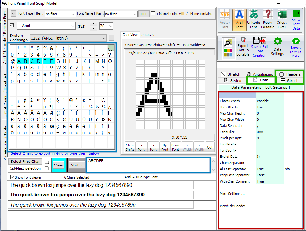
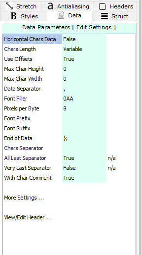
The Data format and Data Structure Parameters for the export of Graphic LCD Fonts have been extended and split in two tabs on the Font Panel.
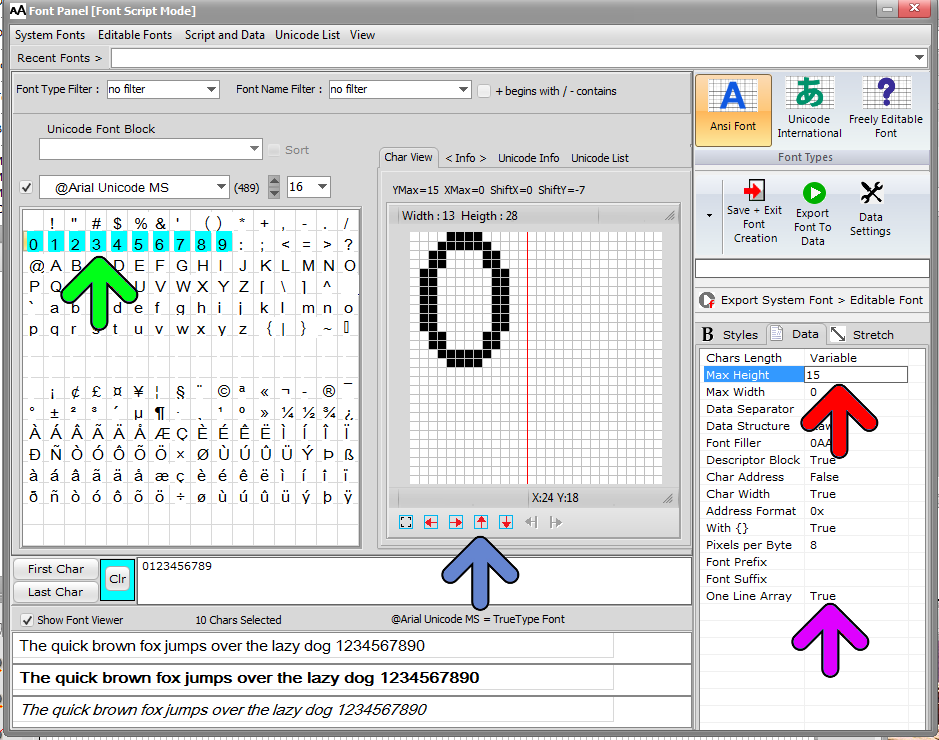
The Tab names are Data and Struct and Header
There’s a choice between 4 different GLCD data structures.
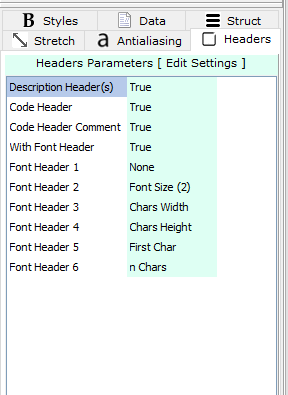
The Font character descriptors / Font Char Header information / can optionally be enabled or disabled and their order of appearance in the code defined.
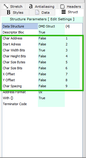
CharacterDescriptors / Font Char Header
Switch the needed descriptors to True or False, if you need them or not in your code export. the adjust then order of their appearance in the code at the right.
Char Adress : It’s the Ascii Code of the Char (In the case of Editable Custom Fonts, you can adjust the Ascii Offset in the Data Parameters to adjust the Char address.
Start Address : Start Address of the Data array of the char.
Char Width Bits : Width in bits of the char.
Char Height Bits : Height in bits of the char.
Char Size Bytes : Size in bytes of the char.
Char Size Bits : Size in bits of the char. Example : If the bottom right pixel of the char is X18 , Y31 (in the Char Grid of the Font Panel) + the X0 Y0 bits, so 19 bits in width x 32 bits in height, the Char size in Bits is 19 x 32 = 608 pixels
An X and Y Offset system is available to remove lines of blank pixels in the code ( char background ) and save memory space. The blank lines at the top and at the bottom of the data are removed from the code output and replaced by Offsets in the descriptors.
Char Spacing : Spacing adjustment in pixels chars.
For this subject, also read this article about character spacing with kerning pairs :
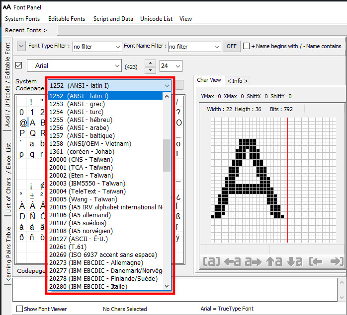
There’s a default/active Codepage installed in your basic Windows installation. The active Codepage depends on your Region/geographic location.
On the ANSI Font Panel, a System Codepagecombobox allows a quick selection of the ANSI Font character encoding without the need to modify the Windows installation.
A code page is a character encoding and as such it is a specific association of a set of printable characters and control characters with unique numbers…
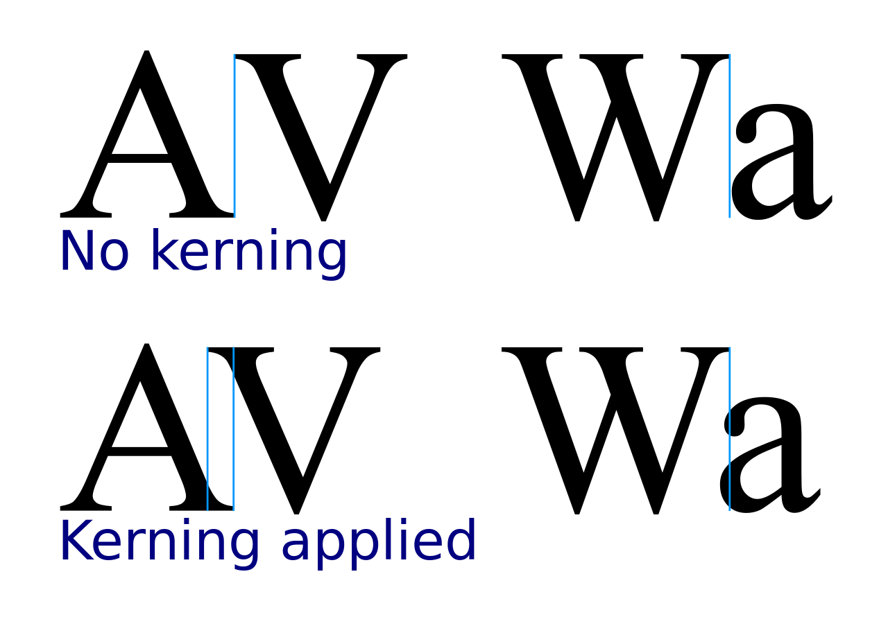
In typography, kerning is the process of adjusting the spacing between characters in a proportional font, usually to achieve a visually pleasing result. Kerning adjusts the space between individual letter forms…
From Version 4.0 Extended Edition , a new Kerning feature has been implemented in the Bitmap2LCD software tool.
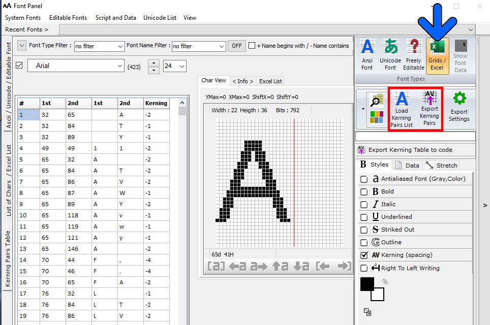
For its use on microsystems with Graphic LCD (GLCD) , the table of Kerning Pairs (1st char, 2nd Char, Pixel Shift in X) corresponding to a particular Font Name, its size and style (Bold, italic..) can be exported to a file as source code
Export > Bitmap2LCD Extended Edition only !
Click Grids/Excel Button
Load the Kerning Pairs List for the current Font and Font Size
Export the Kerning Pairs List to Source/Text file
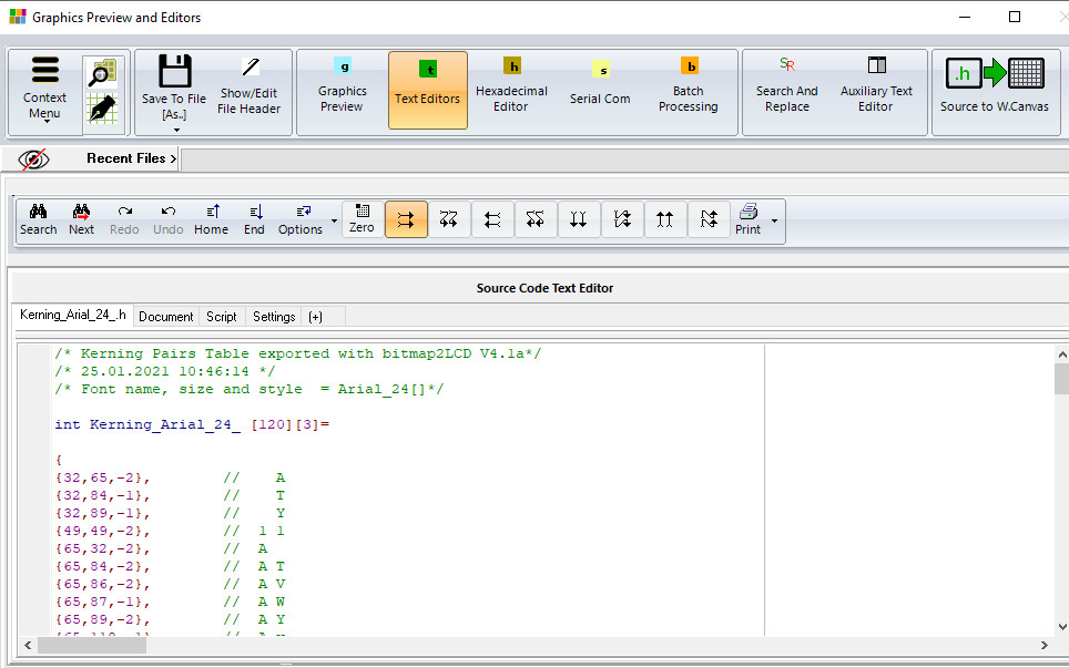
Kerning Pairs Export inside the Editor (Graphics Preview and Editors Window)
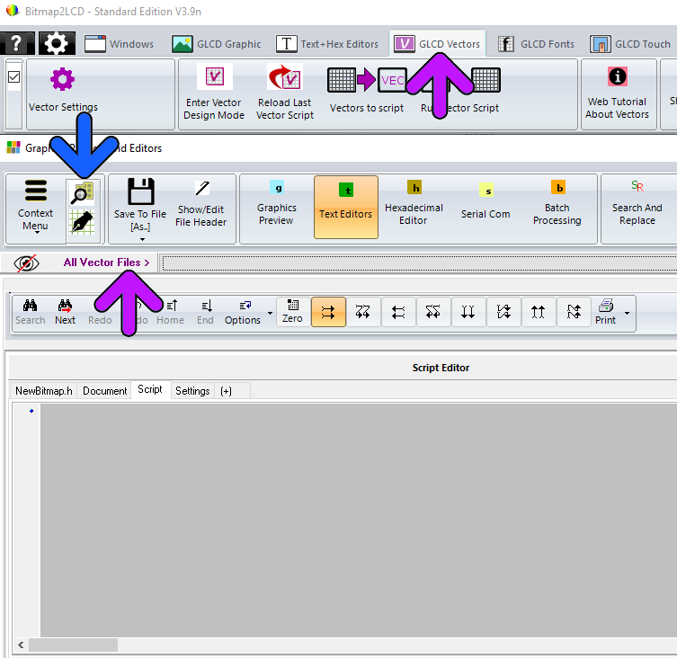
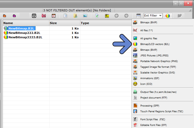
GLCD Vector Programming script files (*.B2L file ext) are stored in the user defined Graphics Files folder and can be loaded into the script editor using the File explorer (blue arrow).
From version V3.9n , when the GLCD Vector Tab in the main menu is active, there’s a quicker way to load an existing vector script file: All the B2L files found in the Graphics Folder are listed in a combobox (Purple arrows)
GLCD Vector Script Menu bar
From version V3.9n, the vector script menu bar has been upgraded with new items. (blue arrow)
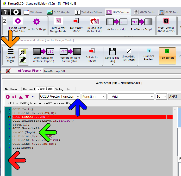
List of GLCD Vector Functions to import in the script
List of basic functions (f.e sleep/pause, calling a subprogram)
Current ANSI Font + Font size or Editable Font to load into script
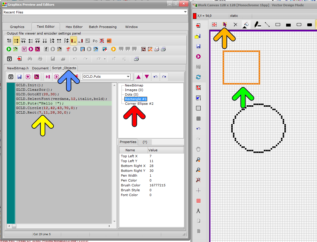
Simultator/debugger functions and other features have been added (see context menu (Orange arrow)
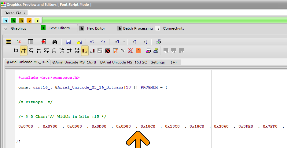
Debugger allows to set breakpoints by clicking the script line inside the gutter (Red arrow) and to ignore/include (Ctrl+i) a script line at script running time . (Green arrow)
Bitmap2LCD is a tool for programming small Graphic LCDs in embedded systems and a programmable graphic and text processing tool.
Bitmap2LCD : Vector Design Module ( General Information )
Programming example below
Update V3.9 upwards
From Version V3.1 Bitmap2LCD is capable to run / generate code which is compatible with external vector Libraries such as GLCD.C , for example one of the many GLCD library you can download for free or buy on the Internet.
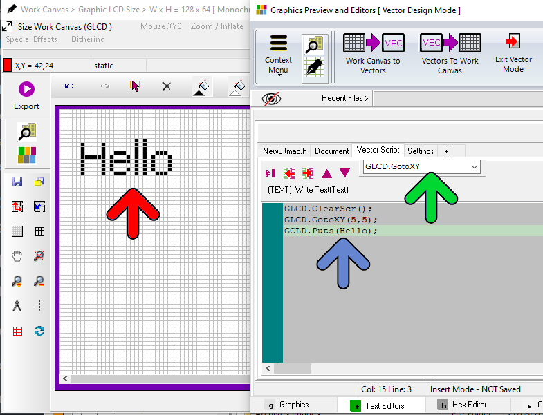
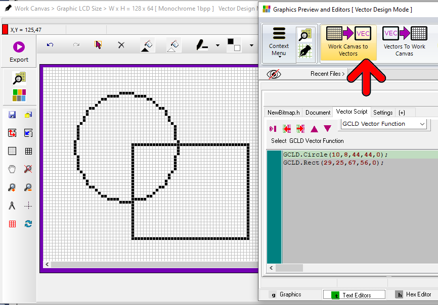
Drawing for example a Line , a circle, an ellipse or a Rectangle on your Graphic LCD becomes very easy : You just have to draw these vectors inside the Work Canvas of Bitmap2LCD (red arrow), and the tool generates the code with its coordinates. Another option is to program vectors inside the script editor and run the script in the same way as with a Graphic LCD Simulator.
This code can be exported to the Text Editor for an external use or can be moved to the Vector Script (blue arrow).
Draw Elements in the Work Canvas < —-> Programm Vector Elements in the script
Draw Vectors Elements inside the Work canvas >> Export Code inside Text editor
Draw Vector Elements inside the Work canvas >> Export Code to the Current Vectors Script
Program Vector Elements inside the Script editor >> Run Script which is Drawing Vector elements inside the Work Canvas
There’s is a list of Vector design Elements (green arrow) you can select and then edit each of its parameters.
The vectors Elements are functions to draw a bitmap, to move the cursor, to write a number, a char or a text, to select a font with its size and style, to draw a dot , a line a rectangle or a circle etc…
The syntax of these Vector Elements can be changed in the Settings Panel to match your particular GLCD library. It’s easy then to copy the script as it is already and paste it inside your embedded app source editor.
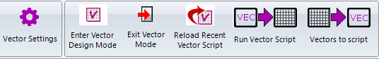
Buttons :
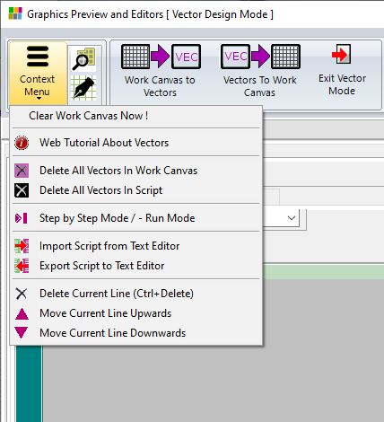
Context Menu :
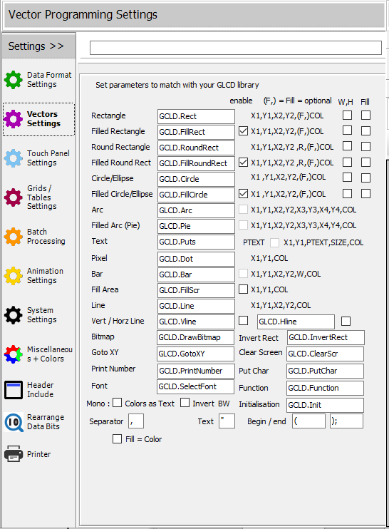
The Vector Programming Settings Panel :
In the Vector Data Settings Panel, you can set the following parameters : The Syntax of the Vector Element function, define if enabled or disabled, define if X and Y coordinates only or with length and width, where applicable, with or without fill (color) parameter. The defined syntax will also appear as defined here in the list of Vector Elements above the Script (green arrow above fig.)
Programming Example
With in the main menu, you can enter the Vector Design Mode.
In the Vector Design mode, the frame around the Work Canvas becomes purple.
Draw a rectangle and a circle vector in the Work Canvas2
Export Work Canvas to Vectors (red arrow)
Vector Script has been generated
Clear the Work Canvas with the delete cross or using the context menu item
Export Vectors To Work Canvas
Work Canvas has been updated from Script
Vector Elements are selectable to be edited/moved, selectable in the Work Canvas or in the Script tables (see below)
Loading / Saving Vector Files
Saving and loading Bitmap2LCD Vector Design files (Files with .B2L extension)
The Vector Elements inside the Work Canvas are saved to a .B2L file. These Vector Elements can be reloaded and edited later, if needed.
B2L Vector Files are saved inside the user defined Graphics Library Folder
See below how to activate the filter to view only the Vector Files inside the File Explorer.
In the Vector Design Mode , you can see the parameters of every vector Element inside the ‘Script + Objects‘ tab located in the Text Editor Main Tab (blue arrow).
Select a Vector Element in the Vector script
You can select them (red arrow) and the selected vector becomes orange inside the Work Canvas.
Select a Vector Element in the Work Canvas
Orange arrow points the Select Vector Element button, the yellow arrow points to the two last lines of the script. These are the rectangle and the circle drawn in the Work Canvas and exported to the script.
Formats of the Vector Elements ( syntaxes are user definable )
GLCD.Dot or GLCD.SetPixel (X,Y,Color)
GLCD.Rect (X1,Y1,X2,Y2,Color)
GLCD.FillRect (X1,Y1,X2,Y2,Color)
GLCD.RoundRect (X1,Y1,X2,Y2,R,Color)
GLCD.FillRoundRect (X1,Y1,X2,Y2,R,Color)
GLCD.CIrcle (X1,Y1,X2,Y2,Color)
GLCD.FillCircle (X1,Y1,X2,Y2,Color)
GLCD.Line (X1,Y1,X2,Y2,Color)
GLCD.VLine (X,Y,Height,Color)
GLCD.HLine (X,Y,Length,Color)
GLCD.DrawBitmap (Filename.bmp,X,Y)
Filename of bmp file located in the Graphics files folder. > no folder name allowed here !
GLCD.DrawBitmap (Filename*,X,Y,Width,Height)
* filename of converted *.h file located in the output files folder but without extension,
No folder allowed here, data direction and endianness must be set correctly : this operation uses the data to graphic conversion ! Currently only monochrome data files supported !
GLCD.GotoXY or GLCD.CursorTo (X,Y)
GLCD.Puts (“text”)
” are optional and definable
GLCD.PrintNumber (numeric value)
GLCD.InvertRect (X1,Y1,X2,Y2)
GLCD.Putchar (character)
GLCD.ClearScr ()
Delay (mS) >> max 5000 mS
GLCD.SelectFont (System Font Name, Font Size, Font Styles (max 4x)*)
*Font styles are : Bold, Italic, StrikedOut, Underlined
Currently only System Fonts supported
Monochrome :
Color = 1 is white
Color= 0 is black
Select and modify Vectors
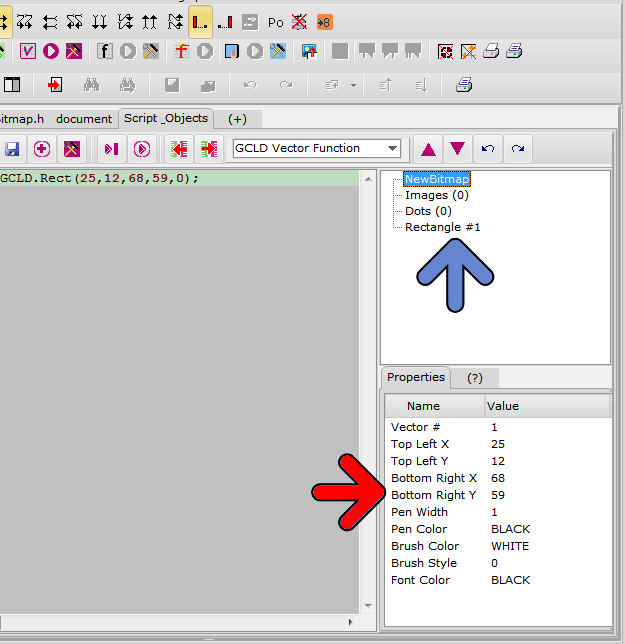
At the right side of the Script and Objects panel, there’s a vector tree where you can find the list of the vectors having been drawn inside the Work Canvas. By clicking on a vector (blue arrow), the list of its Properties appears in the Properties view. (red arrow).
In the Properties View, you can edit the X and Y coordinates and if available, the corner radius of the selected vector.
The vectors programmed inside the script, do not appear in the vector tree and Properties list.