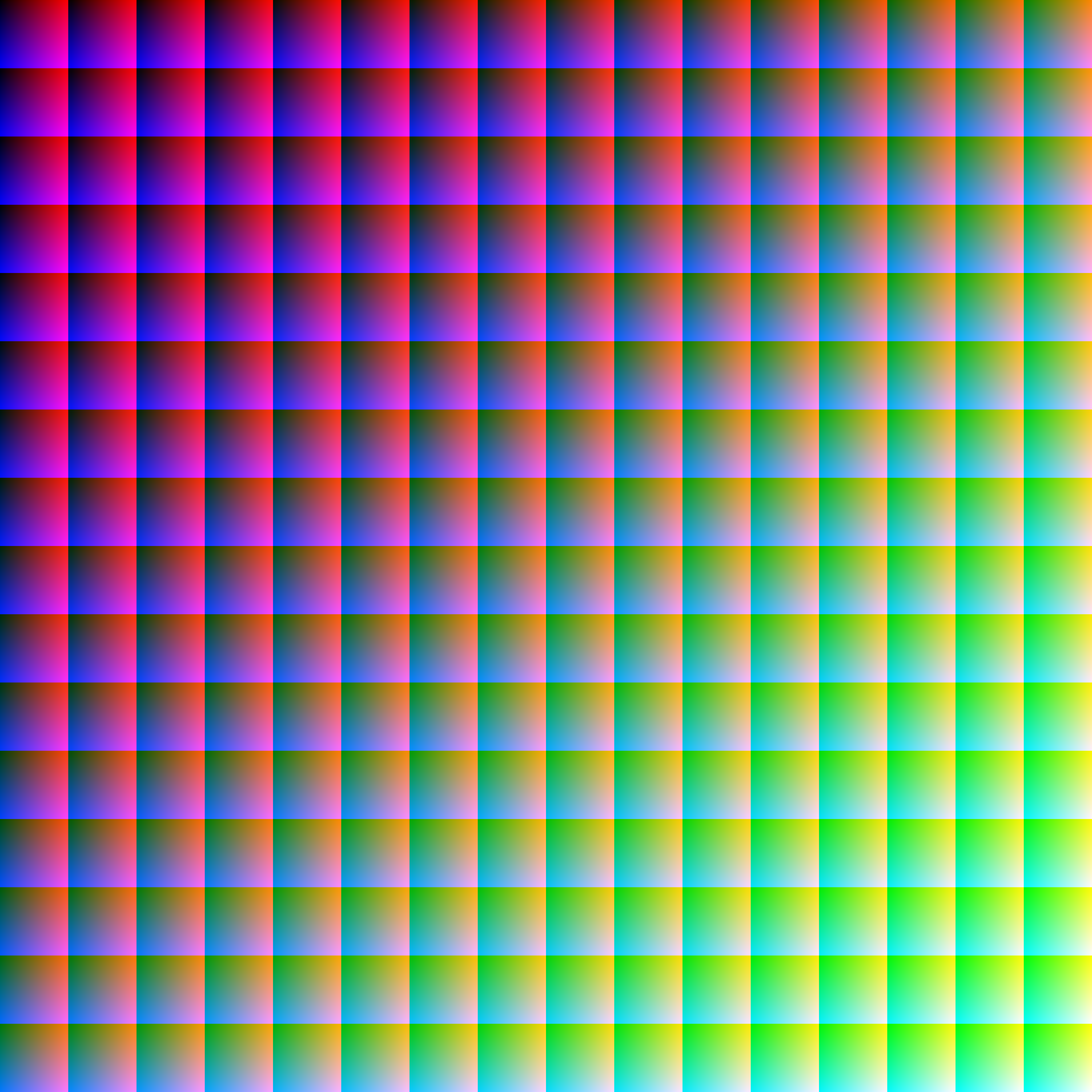
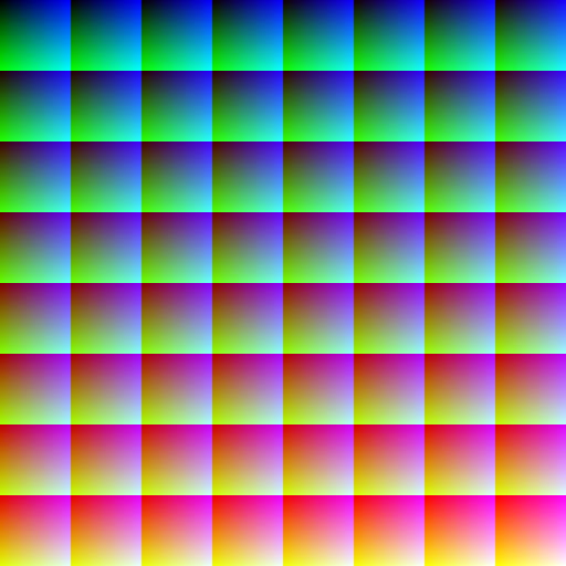
Bitmap2LCD : Reference Graphics for Color Palettes
256 colors ( 8bpp )
4096 colors ( 12bpp )

(262k) 262144 colors ( 18 bpp )
(16 Million) 16777216 Colors ( 24 bpp )
256 colors ( 8bpp )
4096 colors ( 12bpp )
(262k) 262144 colors ( 18 bpp )
(16 Million) 16777216 Colors ( 24 bpp )
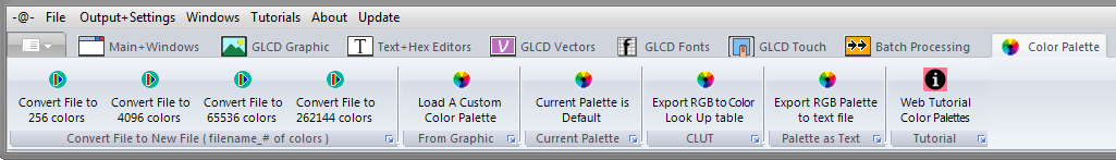
From V3.8e , the above functions have been moved to the COLOR PALETTE tab , Main Menu
In the Output + Settings / Main menu, for the color mode range going from 256 to 262k Colors you can load a Custom Color Palette by loading a graphic file (BMP/JPG/PNG) that contains the exact number of reference colors, for example 256 Colors for the Custom 256 colors Palette.
The “Custom Color Palette” will override the “Default Color Palette” in a particular project other than Default.LCD (see below about projects)
To load a custom color palette, just create/switch to a project different than Default.LCD and switch to the correct color mode (for example 256 colors), then click on the “Load a custom Color Palette” item in the Output + Settings main menu (blue arrow). The Color Palette of the Reference Graphic will then be loaded.
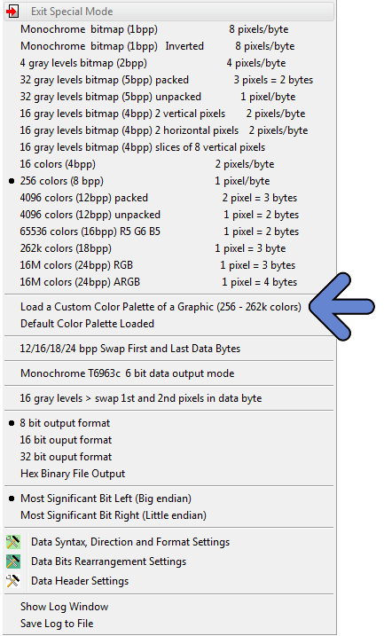
The next line in the main menu, below the blue arrow will show you if the Default or the Custom Color Palette has been loaded.
To delete a Custom Color Palette, delete the project name, for example, MyProject.LCD
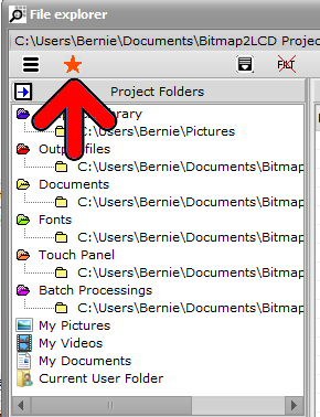
In the File Explorer >>
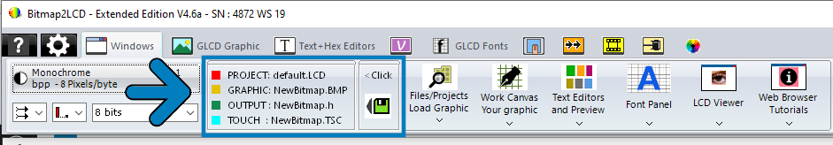
List the projects (red arrow)
Name of the current active project (blue arrow) >> NewProject.LCD
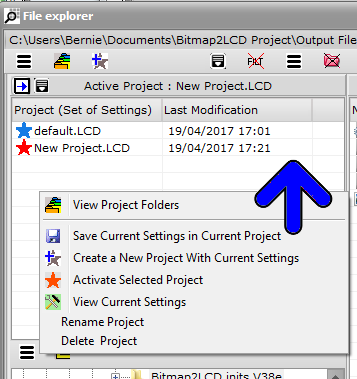
Below the List of Projects ( each project is a set of many possible settings )
A Red Star indicates the active project name
Use Right Mouse Click or local menu to act on projects.
From V3.8e , the above function has been moved to the COLOR PALETTE tab , Main Menu
( From V3.2e Build 4 to V3.8d )
In the Output + Settings main menu, in the 256, 4096, 65536 and 262k Colors mode you can export the default or custom Color Palette to a text file. ( RGB 24bit Color Hex codes )
The exported file will be saved in the project output files folder
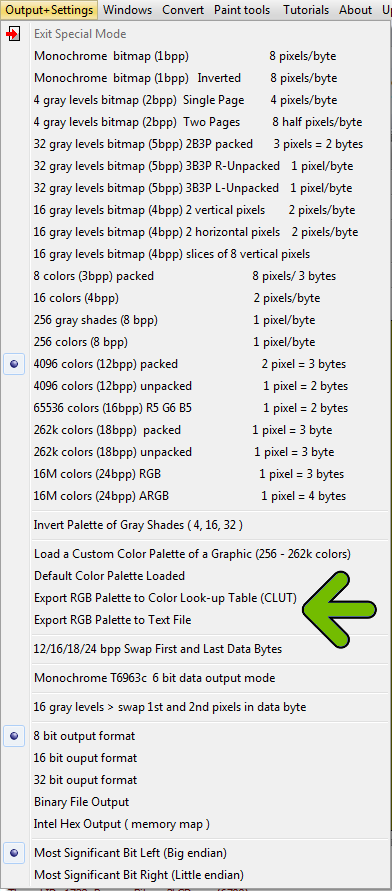
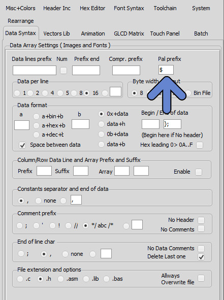
The prefix of the RGB 24bit Color Hex codes can be defined in the settings ( data Syntax Tab )
Bitmap2LCD is a tool for programming small Graphic LCDs in embedded systems.
Bitmap2LCD V2.1b and upwards supports the Sitronix ST7528 grayscale GLCD
The Sitronix ST7528 is a 16-Grey Scale Dot Matrix LCD Controller/Driver
< Quote >
The ST7528 LCD controller does not address rows directly, but rather groups of 8 rows in pages. The LCD memory on the controller is organized into 13 8-bit pages and 160 four-bit column addresses.
There are commands to set the starting page address and column address for a write operation, but no commands to select a row address – you must determine what page the row you want to write is in and set the page address that includes that row. This also implies that if you want to write pixels on adjacent pages, you must address the first page and column(s), write the data, then increment the page address to write the pixels in the adjacent page.
The controller also happens to use what seems like a very bizarre way to load pixel data. Logically, once the address is set, you would write the 4-bit pixel data (or maybe write 2 pixels at a time with a single byte). However, since the addressing scheme addresses pages and not rows, this approach is not used.
Instead, one bit of data for the entire addressed column of pixels (8 vertical pixels) in the current page is written with each byte sent to the LCD. Since each pixel requires 4 bits of data to define the grayscale level, 4 bytes of data must be sent per column to fully define the bits. While this data is being clocked in, the “main” column address does not change. Only after the fourth bit is written to a column is the main column address pointer automatically incremented inside the LCD controller so the next 4 bytes of data sent to the LCD will write the bit data for the next column.
To be complete, we must comment that the “column address” that you send to the LCD controller is actually bits 9:2 of a larger column address inside the controller. The bottom two bits 1:0 are “internal column” address bits. When the 4 bytes of data are written to the LCD controller by the MCU, the internal column address bits increment after each byte write. After the fourth byte is sent, the internal bits will roll from b’11’ to b’00’ and subsequently increase bit 2 of the column address. As you can probably guess, if you do not write LCD data to the controller in groups of 4 bytes, than you will not have complete data for the pixels and the internal LCD addressing will be corrupt.
The implication of all this is that you cannot ever write a single pixel on this LCD. The smallest number of pixels that can be refreshed is a 1 column x 8 row line and it will always take a minimum of four bytes sent to the LCD controller from the MCU to properly set those pixels. If you really do only want to update one pixel in the 1×8 column, you must be sure to write the same data that is already present for the other 7 pixels so their information does not change. This is where keeping a local copy of all pixel data in the LCD RAM becomes essential as individual pixels can be changed in the local RAM as the application requires it, and pixel data for unchanged pixels will still be present for the LCD refresh…
< End of Quote >
Quote from this well written Application Note : ST7528 Appnote
From Bitmap2LCD Version 3.0H
When converting a picture into hex data for a graphic LCD of 160 x 100 pixels , you will get 8320 Bytes, in vertical slices of 8 pixels in height. ( Normal Gray 4bpp Mode outputs slices of 2 pixels in height = 8000 bytes of data )
——-
Before Bitmap2LCD Version 3.0H
Here’s the needed configuration of Bitmap2LCD for a data output for the ST7528 :
When converting a picture into hex data for a graphic LCD of 160 x 100 pixels , you will get 8320 Bytes, in vertical slices of 8 pixels in height. ( Normal 4bpp Mode outputs slices of 2 pixels in height = 8000 bytes of data )

Other special Modes for the following Sitronix LCD controllers are planed in future upgrades :
4-Gray Graphic : ST7541 , St7571
32-gray Graphic : ST7529 , ST7586
Bitmap2LCD is a tool for programming small Graphic LCDs in embedded systems and a programmable graphic and text processing tool.
Update >V3.9a
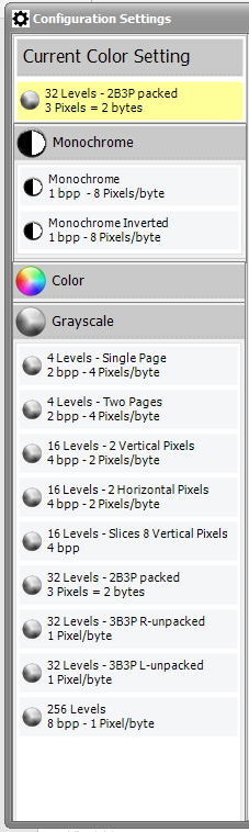
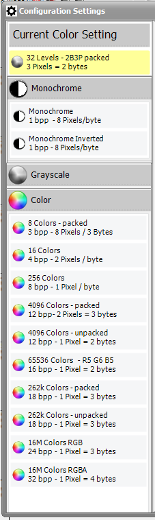
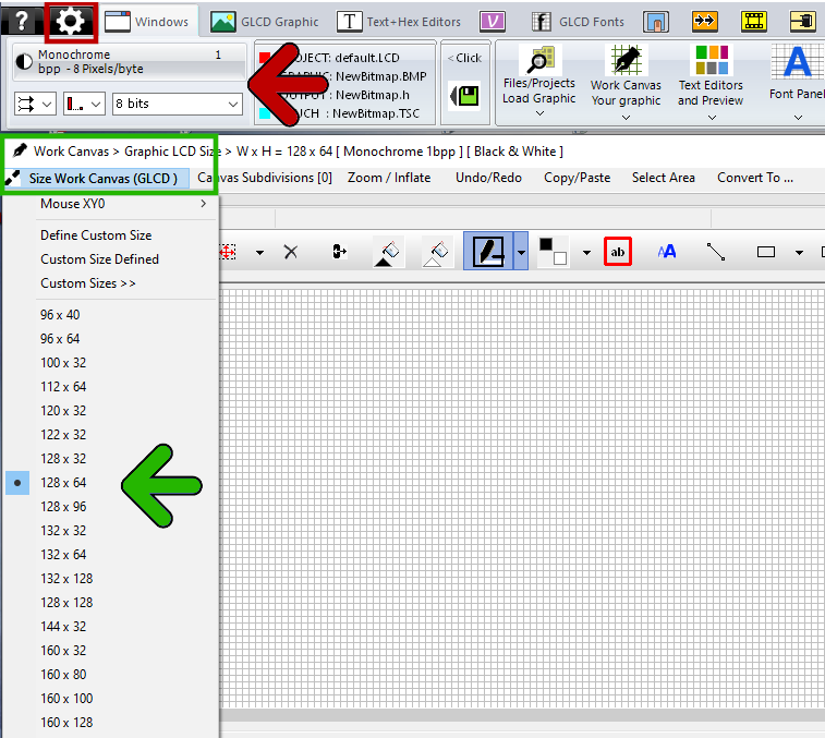
From Version V3.9a the Configuration Settings have been moved to a single panel accessible from the main menu. (red Arrow)
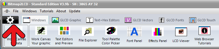
The Monochrome / Grayscale / Color Setting can be found in the same Window
Versions V3.8a – V3.8z
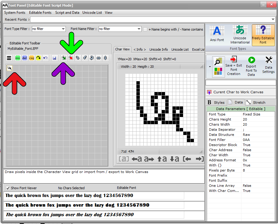
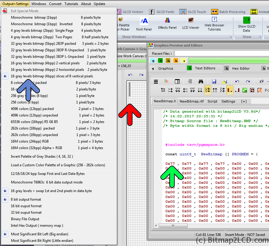
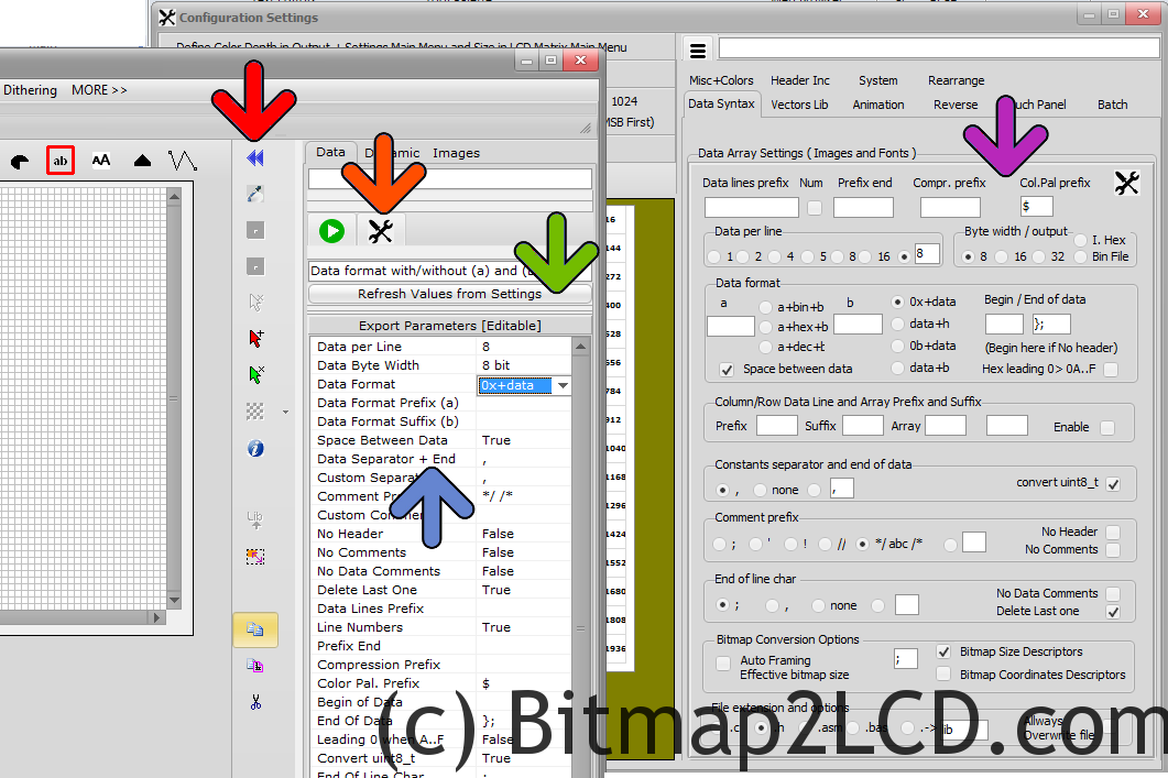
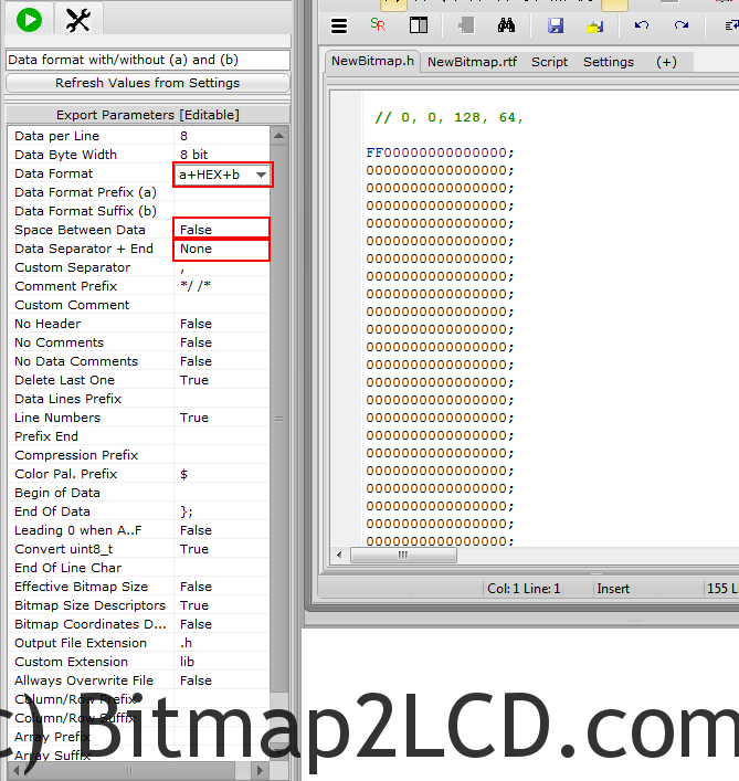
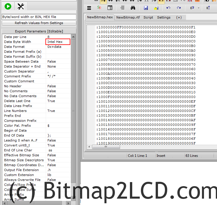
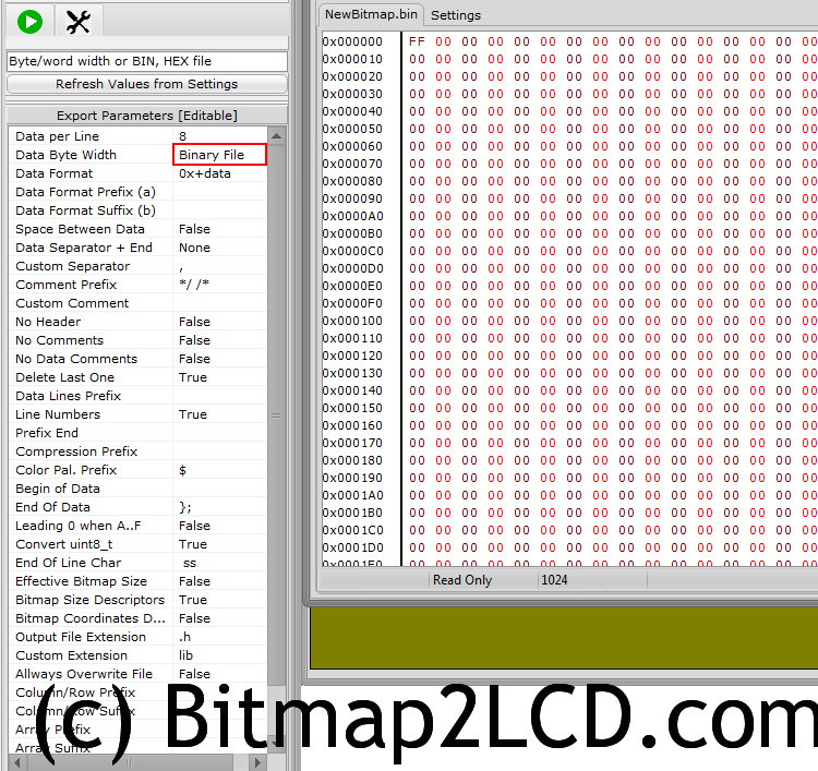
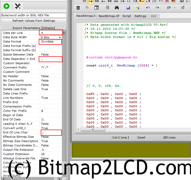
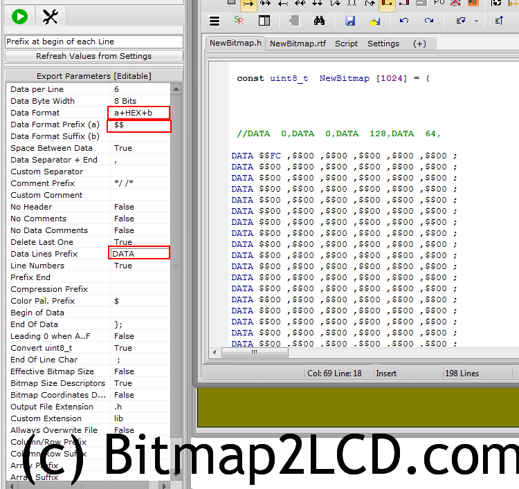
From V3.8a, the parameters (blue arrow) located inside the right panel of the Work Canvas ( hide/ show > red arrow ) are editable.
The Export To Data Settings are the same as those located on the Configuration Settings Windows. (purple arrow)
Note : Some of these settings are also valid for the Fonts Generator !
You can change the export settings from there (blue) . Their value will be copied to the Configuration Settings Windows (purple)
If changes are made in the Configuration Settings Windows, the values might be refreshed (Refresh Values from Settings > green) on the Work Canvas Panel
Bitmap2LCD is a tool for programming small Graphic LCDs in embedded systems and a programmable graphic and text processing tool.
Update V4.7b >
Presentation of Bitmap2LCD (Youtube)
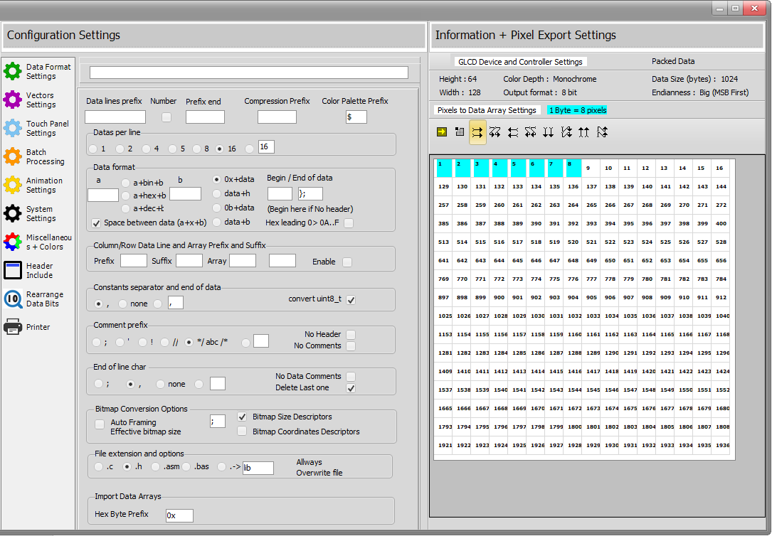
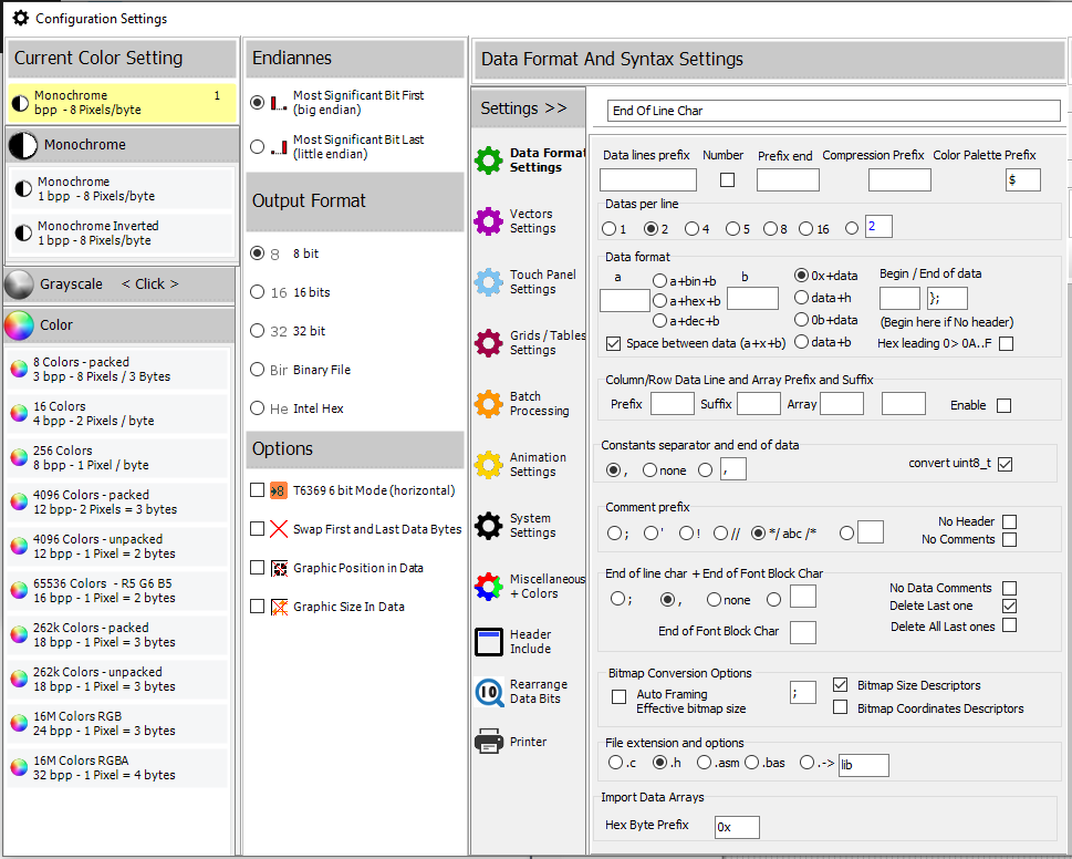
Configuration Settings : Monochrome, Color and Grayscale, Data formats etc…
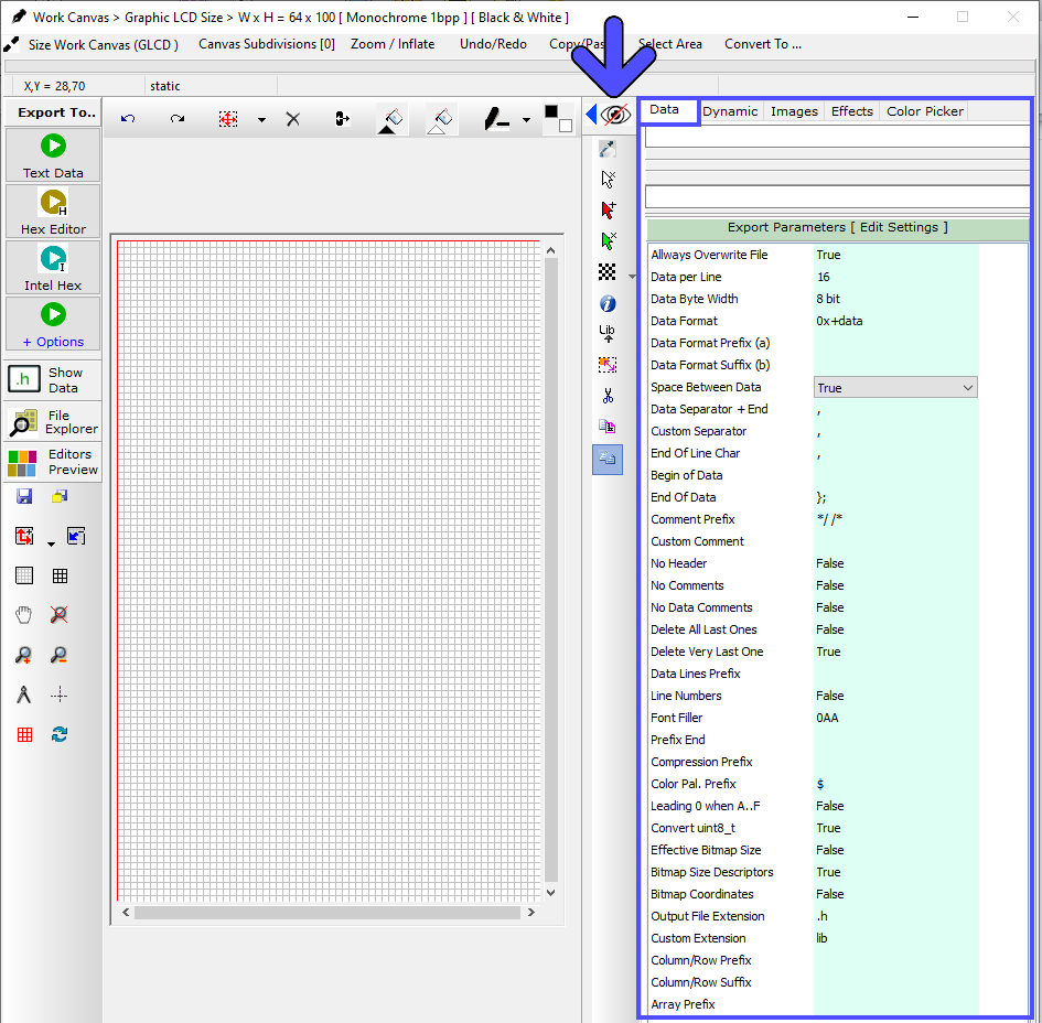
The Data Format Settings are also located in the right panel of the Work Canvas. (blue arrow and frames)
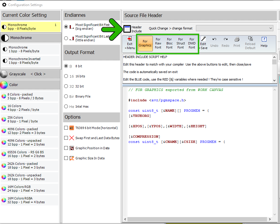
Output File Header
Note : the variables with the [&xxxxx] syntax are optional script components, replaced by their value on export. (details at the end of this article)
update V3.7f
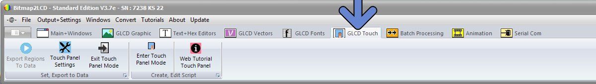
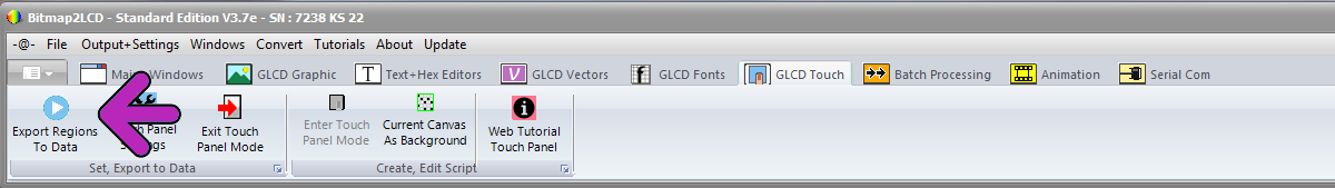
Touch panel settings 
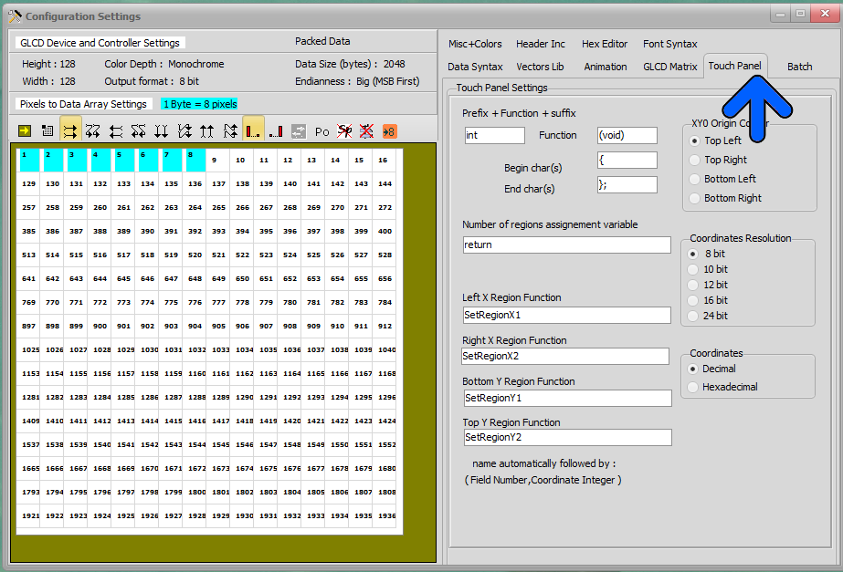
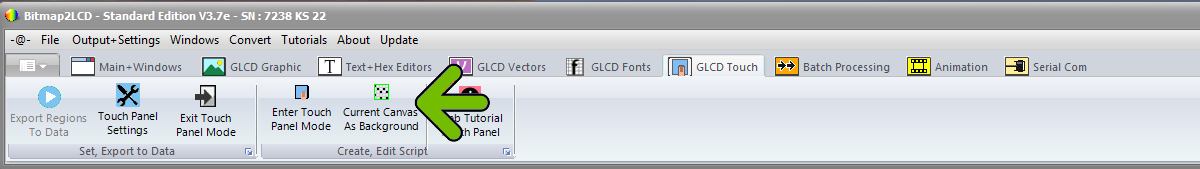
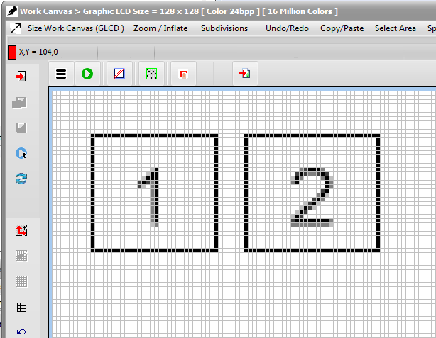
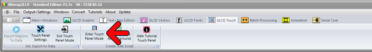
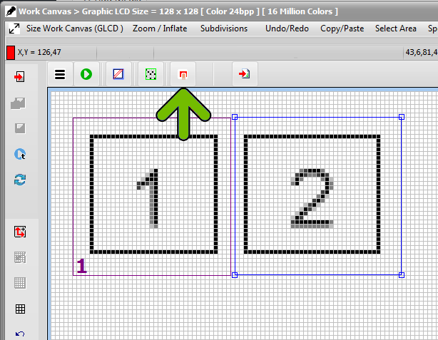
To trace Touch panel regions inside the work canvas, after entering in the touch panel script or by opening the TSC file ( Work canvas outline becomes light blue ) use the mouse inside the work canvas in a similar way to the area selection tool.
Trace the region and when ok, click on the convert to region button (green Arrow)
Theses regions can be moved or resized afterwards.
Bitmap2LCD is a tool for programming small Graphic LCDs in embedded systems.
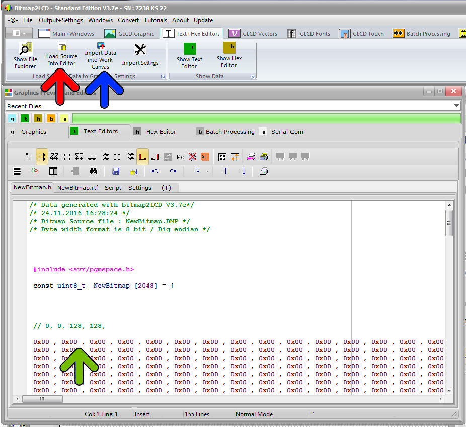
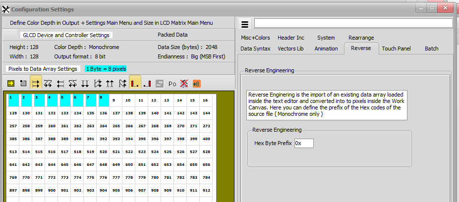
Reverse engineering : Convert an existing Data Array (or Hex File) to a Bitmap
Update V3.7e , monochrome only
Want to convert 8 bit GLCD data array from an old project to a 16 bit GLCD data array in a new project ?
Want to recover the image from of an old GLCD data array source ?
For monochrome GLCD data arrays of 8, 16 and 32 bit – bytes/words – , it is possible with bitmap2LCD !
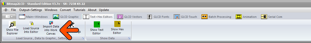
Set your work Canvas Height and Width to a compatible size with the number of data in the array loaded in the text editor, set the byte word Width to 8 16 or 32bits (in the output main menu) , select the data direction (horizontal or vertical) and click one of the import Data Array buttons. If it matches with the data count, the Work Canvas will show the graphic.
For example in a file an array of 2560 bytes ( 0x00 – 0xFF )
( Width * Height ) Pixels per byte = (160 * 128) / 8 = 2560 bytes
Import the array into the work canvas and save the work canvas as bitmap.
Settings :
Define the Hex byte prefix to be found inside the source file
Bitmap2LCD is a tool for programming small Graphic LCDs in embedded systems.
[ Editable Fonts : up to 256 colors ]
Standard Edition V3.9>
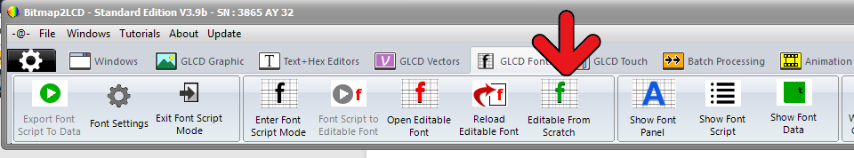
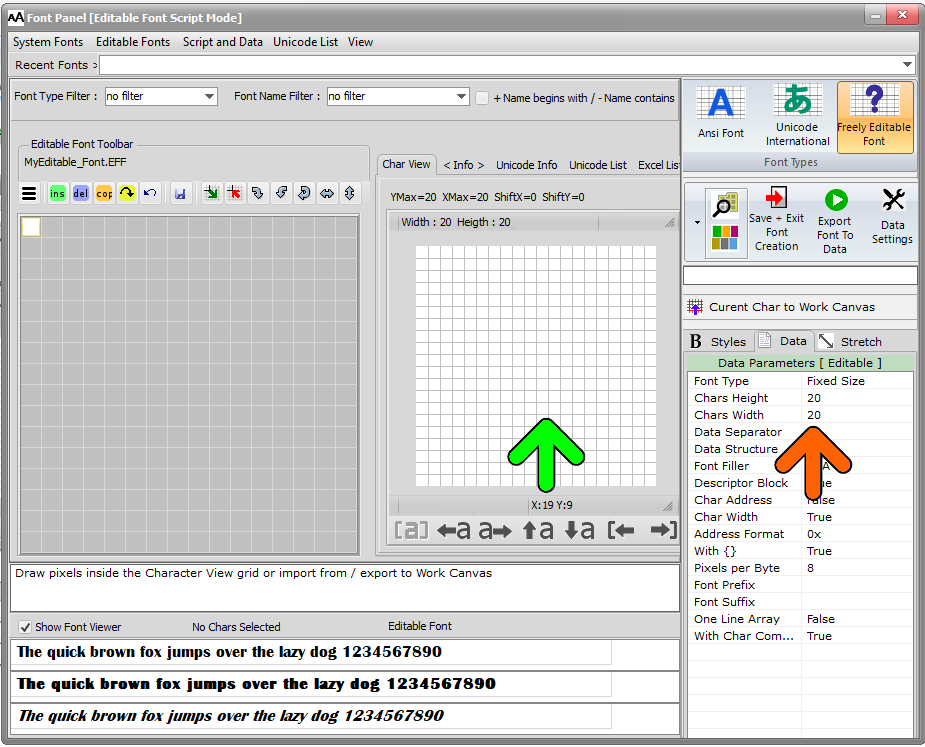
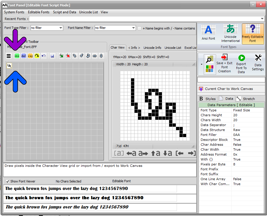
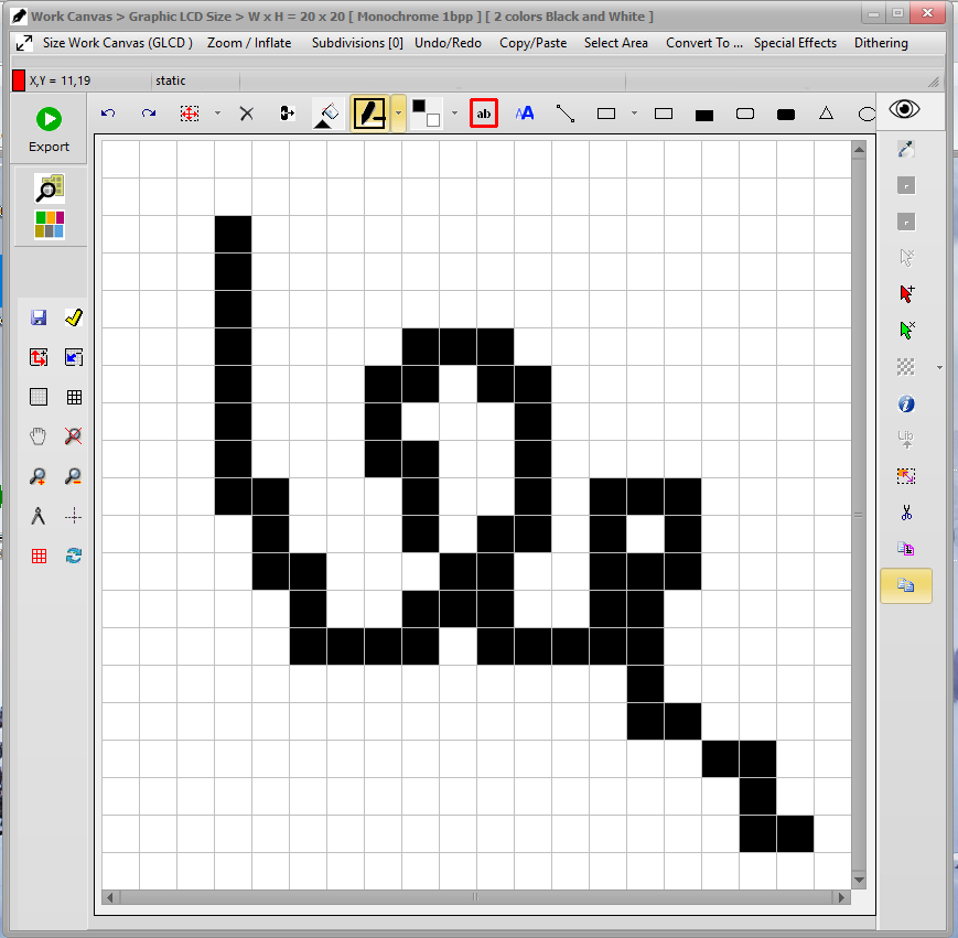
Then use the drop down menu at the left or the buttons (purple arrow) to manage the editable font creation.
You can export and import the selected char to/from the Work Canvas.