An example of an image import and resize in Bitmap2LCD

Bitmap2LCD is a tool for programming small Graphic LCDs in embedded systems.

Let’s see an example of an image import and resize in Bitmap2LCD

  • To import an image, click on the image filename inside the file explorer of Bitmap2LCD
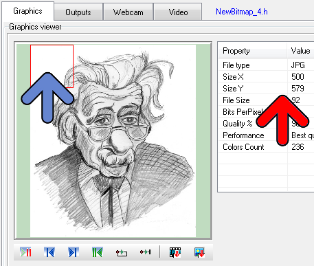
  • If the picture size is bigger as the Work Canvas, ( in this example a 500 x 579 pixels image – red arrow – and a 128 x 128 pixels Work Canvas ) a red frame in a proportional size of the canvas appears in the image preview (blue arrow)
  • Move the mouse inside this red frame in the image preview (blue arrow), and move the frame to the area you would like to import.
  • When ready, click the import image button (the button at the right side below the preview)

  • In the “Resize to fit ?”pop-up message, choose  = NO
  • In this example, Bitmap2LCD converts the 236 “colors” picture to the 16 gray levels for the target Graphic LCD

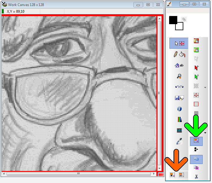
  •  If needed, move the selected area inside the canvas (click & move with mouse)
  • If you want to adjust the size of the image import, click the resize selection button (green arrow)
  • Then use the mouse wheel or the resize area buttons to resize the import (orange arrow)
  • At the end, Paste the selection (Paste Button or Return Key)
Create Segmented Charsets for GLCD with Bitmap2LCD

Bitmap2LCD is a tool for programming small Graphic LCDs in embedded systems.

Create Segmented Charsets for GLCD with Bitmap2LCD

Obsolete, not available on current SW versions

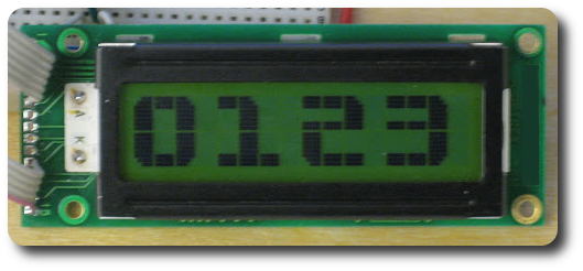
Since V2.2, in the GLCD Font Editor Component of Bitmap2LCD , a feature makes it possible to create segmented fonts, a set of characters that are similar to the 4 numbers displayed on the LCD module in the picture below.

A segmented character is made of an assembly of smaller graphic segments (in this example 6 segments for the O) . These segments being present more than only one time in the different characters of the font.

Now let’s see how this feature is implemented in bitmap2LCD  :

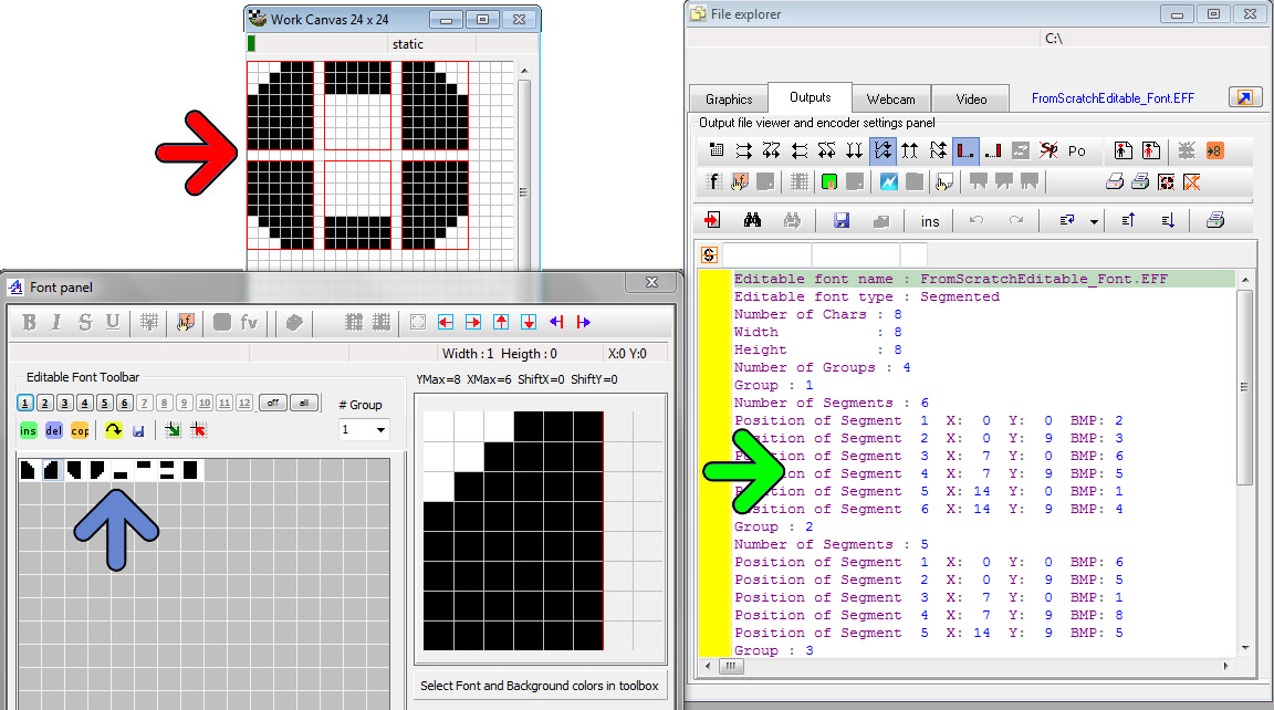
  • View of the char group #1 in the Work canvas (red arrow) The word “group” means an assembly of segments or small graphic elements.
  • The 8 segments needed for the whole charset in the Font Editor Window (blue arrow)
  • The Segment Font Script for this font. This file contains for each character (group) the X and Y positions of all graphic elements and their associated segment bitmap.


Description of the GLCD Font Editor in Bitmap2LCD

Bitmap2LCD is a tool for programming small Graphic LCDs in embedded systems.

Description of the GLCD font editor in Bitmap2LCD (since V2.2)

Standard Edition

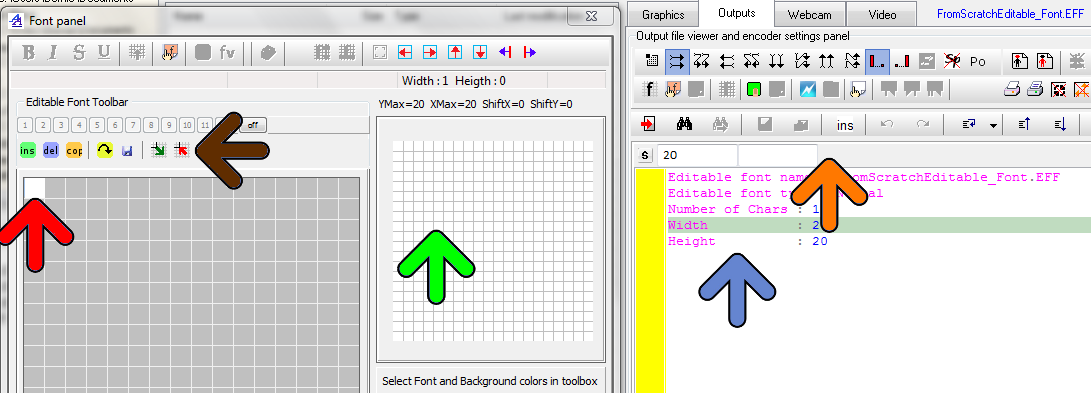
The example below shows the begin of the creating of an Editable font from scratch

On the font panel window at the left :

  • There is one single new Char is in the font grid (red arrow), all pixels are white
  • The font editor toolbar (brown arrow) Buttons: insert new char or paste a char, delete a char, copy a char,export to work canvas,import from work canvas, save font…
  • Above the Font Editor toolbar, the segmented font viewer buttons to hide/show the different Char segments (up to 12 segments)
  • The character displayer and pixels editor. (green arrow) For complicated Char edits, the Char can be exported into the work canvas, and re-imported after modification.

On the Outputs panel window at the right :

  • The Editable Font Script in the editor (blue arrow) , in the GLCD Font Editor mode, the editor gutter becomes yellow.
  • The Editable Font Script editor toolbar  (orange arrow), the values in the Font Script can only be modified in the edits there. It depends where the cursor is located in the script. The Normal Font / Segment Font switch is located on this toolbar too.

The GLCD Font Editor in Bitmap2LCD

Bitmap2LCD is a tool for programming small Graphic LCDs in embedded systems.

The GLCD Font Editor in Bitmap2LCD

Standard Edition

Since Standard Edition V2.2 and upwards, Bitmap2LCD features a GLCD font editor

The already before existing font script component, is only based on imports of characters out of  the installed Windows system fonts, with no possibility to edit the pixels.

The new GLCD font editor feature gives this capacity of editing the fonts and/or to create new characters and icons.

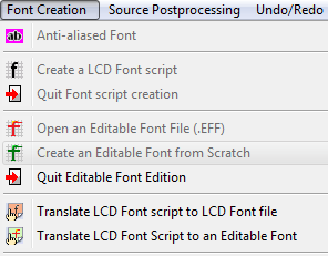
The GLCD font editor component is called “Editable Font ” and the associated functions can be found in the main menu, see below.

  • Open an existing Editable Font File (*.EFF)
  • Create an Editable font from  scratch
  • Quit the Editable Font Edition Mode

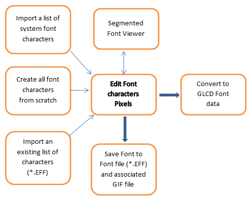
The GLCD font editor possibilities are shown below

[ Editable Fonts : up to 256 colors ]

An Editable Font file created with Bitmap2LCD, is saved in a *.EFF file with his associated GIF file, all single characters bitmaps being saved in the frames of a GIF animation. The GIF becomes a sort of catalogue of images.

The Editable font GIF file can also be displayed in the GIF file reader , like a normal animation. The *.EFF file (Editable Font File) is just a script witch contains additional informations.

When opening an editable Font (*.EFF) , by clicking on it in the file explorer, the associated GIF companion file is opened automatically.

Export a part of a bitmap to GLCD data with Bitmap2LCD

Export a part of a bitmap to GLCD data with Bitmap2LCD

Bitmap2LCD is a tool for programming small Graphic LCDs in embedded systems.

Update => V3.7c

With bitmap2LCD,  you can easily convert a part of an image / picture to hex data for your Graphic LCD Display (partial conversion)

bitmap2lcd-export-selected-area_1

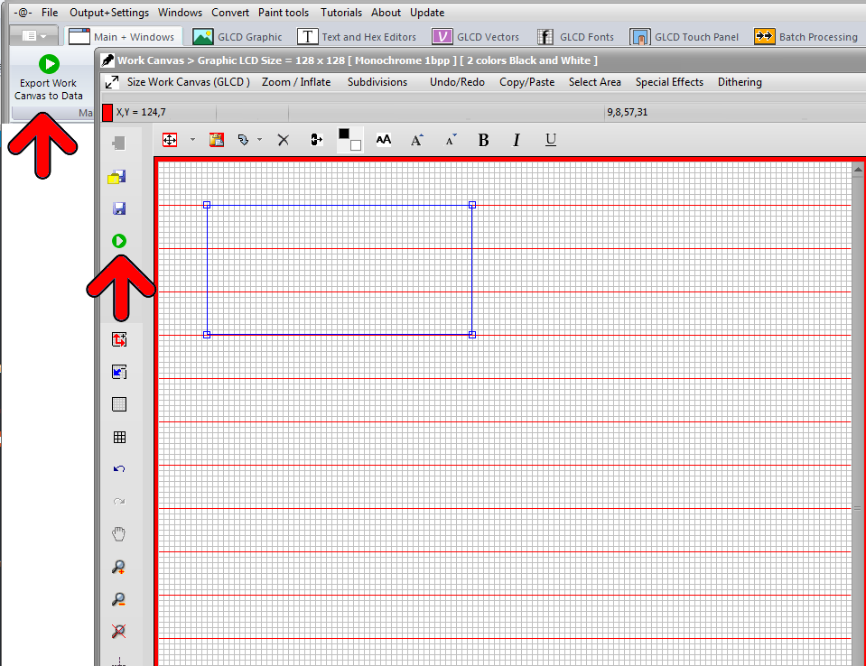
Export Selected Area button (in the main Menu)

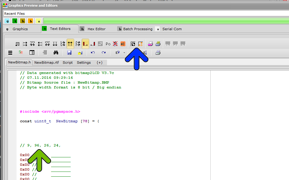
To achieve this partial conversion, use the menu item Export Selected Area of to Data or follow this tutorial…

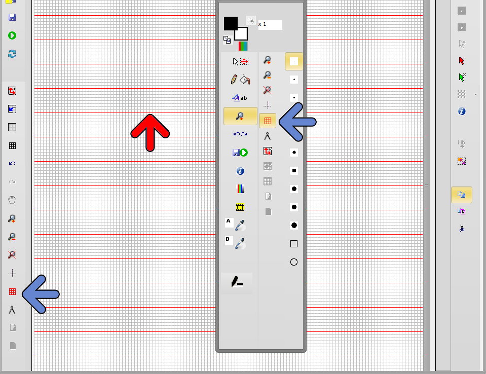
  • Enable the paging scheme display (one of the blue arrows)
  • Red horizontal or vertical lines will then appear in the Work Canvas (red arrow). These lines depend of the selected paging scheme  (horizontal or vertical) and of the pixel data depth ( monochrome , grayscale… ) In this monochrome example, we have 8 pixels / data byte, therefore a gap 8 pixels between the lines.
  • These lines will also act as area delimiters / selection magnets when you later select the area to convert.


bitmap2lcd-export-partial

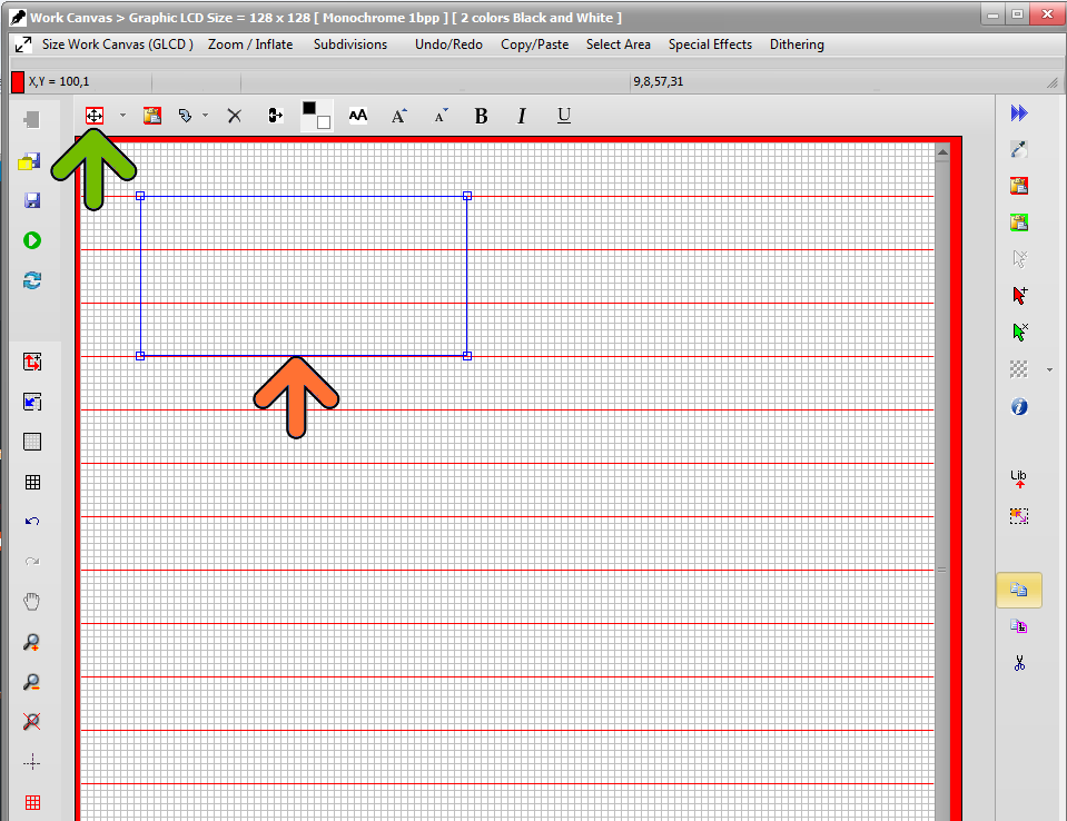
With the selection tool (green arrow) , and with the mouse clicked in the Work Canvas, define the area frame (orange arrow)

bitmap2lcd-export-partial_2

  •  If you want to see or include somewhere the X and Y corner position, the width and the height of the area frame (orange arrow) inside the code (green arrow) set the buttons (blue arrow).  You can also specify the use of these 4 informations within the header include editor.

bitmap2lcd-export-partial_4

  • Start conversion (red arrow)


bitmap2lcd-export-partial_3


The Touch Panel feature in Bitmap2LCD

Bitmap2LCD is a tool for programming small Graphic LCDs in embedded systems.

The Touch Panel feature in Bitmap2LCD

The Touch panel / Touch Screen feature in Bitmap2LCD is to ease the

the graphical definition of the regions and to output the coordinates in the specific resolution and direction (from Origin) given by your touch panel controller.

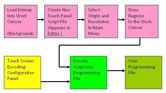
Here’s the roadmap :

In Touch panel script Mode, the editor’s gutter becomes green

Note that the Touch Panel Script can’t be edited in the editor itself !


The Touch Panel Script is then saved as a .TSC file in the defined Touch panel Folder.

You can reopen an existing Touch Panel Script when clicking on the .TSC file name in the file explorer.


Convert a range of unicode chars for GLCD Font

Bitmap2LCD is a tool for programming small Graphic LCDs in embedded systems.

Convert a range of unicode chars for GLCD Font

Obsolete article, only for previous versions < V3.7

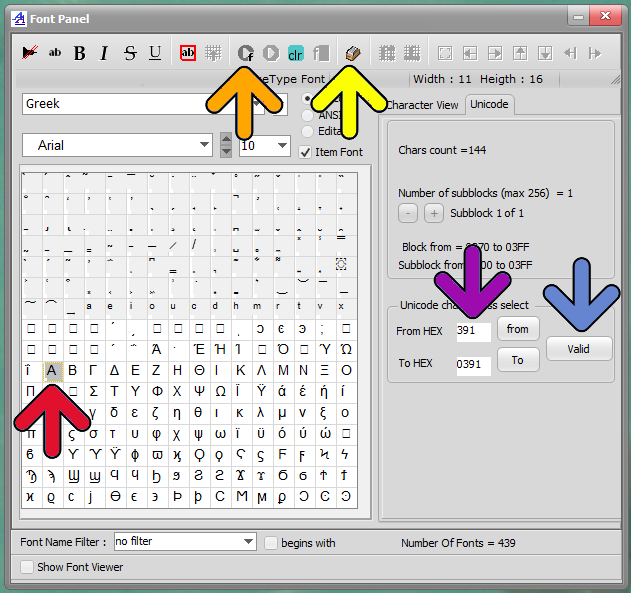
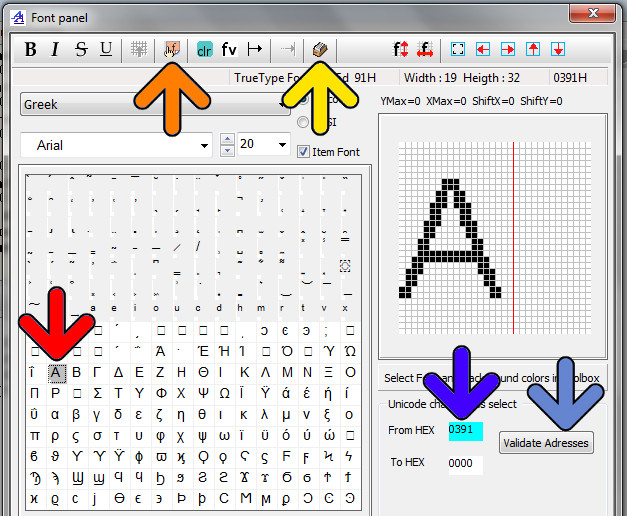
Another way to convert unicode chars by defining a range of them:

  • Enter font script mode
  • Enter Range Mode (yellow arrow)
  • If necessary, erase the from Hex and to Hex addresses with the clr button
  • Select Range Start in the char grid (red arrow), address appears in From Hex (blue Arrow)
  • Select Range End the same way in the char grid -> To Hex
  • Then Validate Address (blue arrow)
  • Encode the Font Range (orange Arrow)

Note : You can define Start and End of range addresses in different Fonts blocks. The condition is that the Start address is below the end address.

Version 3.0+

Bitmap2lcd Unicode Font Range


Before Version 3.0


About the touch panel function in Bitmap2LCD

Bitmap2LCD is a tool for programming small Graphic LCDs in embedded systems.

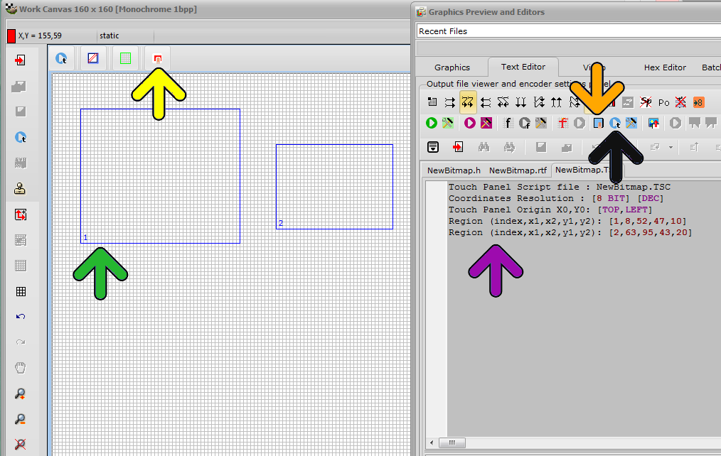
Touch panel regions (green arrow) can be graphically defined in the work canvas.

  • If not already displayed, load the correct bitmap into the work canvas ( sample)
  • Create a Touch panel script (orange arrow)

The editor gutter becomes green = Touch Panel Script.

  • A region can be defined using the mouse with the area selection tool (green arrow)
  • When the touch panel region size and location are correct, convert the area to a region with the “Make touch region” button (yellow arrow)
  • When all regions where defined , convert the script to an output file (black arrow)

Note that you can edit, move, resize defined regions.

Bitmap2lcd Touch Screen Feature

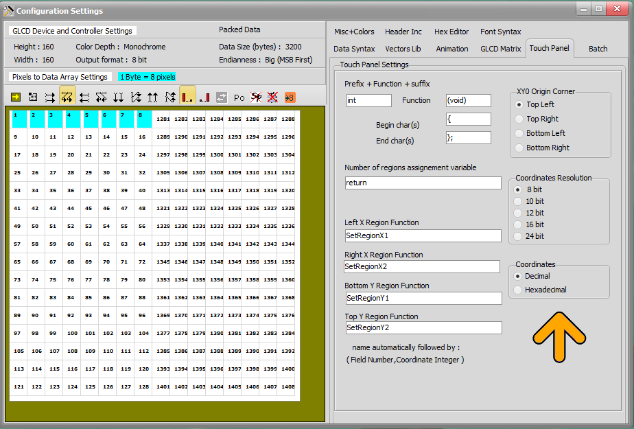
Configuration settings for touch panel data output (see fig2)

  • In the Touch panel main menu (orange arrow) you can define the data direction and the Touch Screen controller resolution (8,10 or 12 bit)
  • In the toolTouch Configuration Settings Panel, under tab Touch Panel, you can define your favorite output syntax.
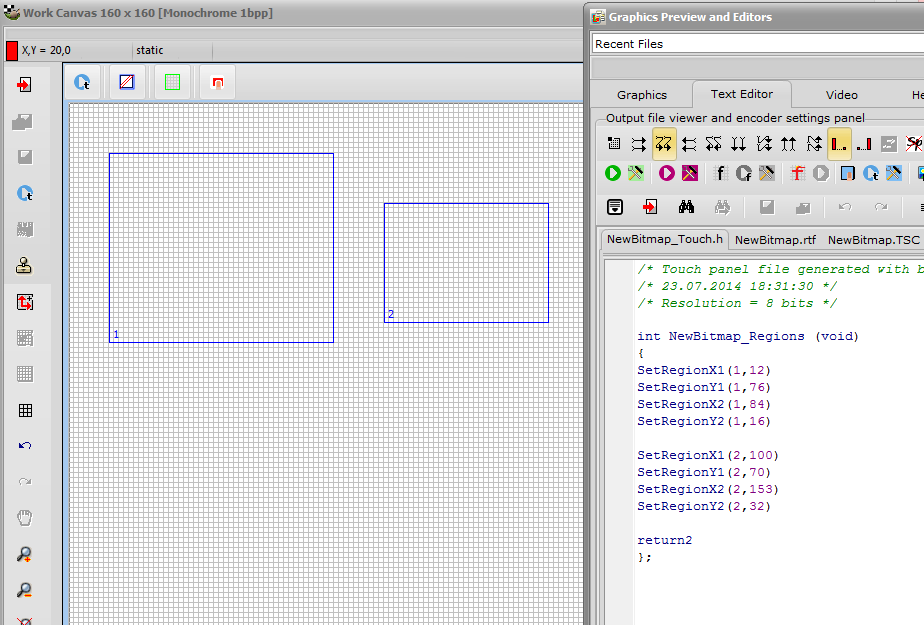
  • When converting the defined regions with the button (green arrow) the data in the editor then contains the regions, with field number and the 4 coordinates of each region.

Bitmap2lcd Touch Screen Settings

Start touch Then convert the Touch Panel Regions to Data :

Bitmap2lcd Touch Screen Data


About the File Explorer in Bitmap2LCD

Bitmap2LCD is a tool for programming small Graphic LCDs in embedded systems.

File explorer files view settings

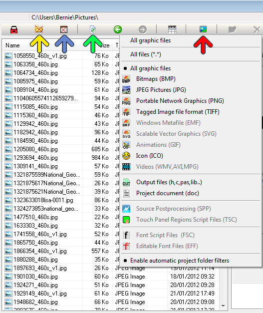
  • include / exclude the folders in/from the list of files ( yellow arrow )
  • include / exclude older than today’s files in/from  the list of files ( blue arrow )
  • Refreshing the list of files, for example after insertion of a USB Stick
  • Filtering the list to only show a family of files. ( fig1. the file filter list is popped up )

If any file list filter is set, in the status bar at the top right side of the file explorer, the count of elements is displayed as NOT FILTERED OUT.

Use the file explorer’s project path in Bitmap2LCD

Bitmap2LCD is a tool for programming small Graphic LCDs in embedded systems.

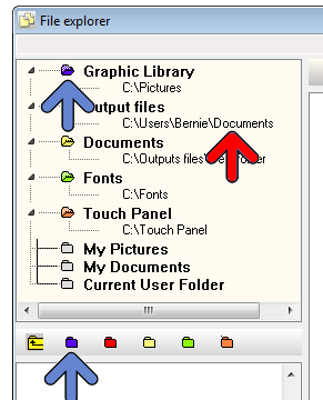
At the top left side of the file explorer, you can set your 5 different project folders.

You can differentiate Graphic files, Output files ,Documentation files, Fonts files and Touch Panel files.

When you’ve selected the folder in the file explorer, click the blue, red, yellow, green or orange icon (fig1. blue arrow at the bottom)  corresponding to the files family, in order to set the path.

Later on, you can either click on one of the the direct links (red arrow) for unfiltered files lists or on the file family (for example upper blue arrow) to display a filtered list. (This files filtering option can be disabled or enabled at the bottom of the filters menu)