Bitmap2LCD : Sizeable Editor separated from the File Explorer

Bitmap2LCD is a tool for programming small Graphic LCDs in embedded systems.

Sizeable Text Editor and Separate File Explorer

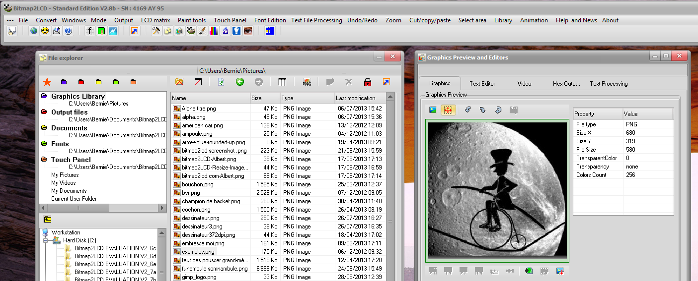
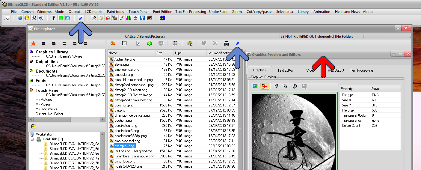
From Version V2.8b, you can split the “File Explorer” and the “Graphics Preview & Editors” (red arrow) into two separate Windows (See button pointed by blue arrows)

Bitmap2lcd Split Editor and Explorer 2

The “Graphics Preview and Editors” Window can then be resized.

Use the same buttons to reunite the windows.

Bitmap2lcd Split Editor and Explorer 1

Bitmap2LCD : Example of moving a group of pixels

Bitmap2LCD is a tool for programming small Graphic LCDs in embedded systems.

Example of moving of a group of pixels

1 . Click Select Contiguous Pixels Button  (red arrow)

2 . Click inside the area of pixels (a group of pixels separated from the others, an island (blue arrow)

–> The seleted group of pixels becomes red

3. Click the Selection Area button (green arrow)

Bitmap2LCD moving Pixels 1

4. Move the mouse cursor inside the selected area (blue arrow) and drag the area to the destination (orange arrow below)

5. Click Paste button

Bitmap2LCD moving Pixels 2

6. To “delete” the moved area, press the escape key ( to clear the addition of pixels to the last selection)  and press the delete key (in this case the background color should be white )

Bitmap2LCD : Replace a color with another in the entire Work Canvas

Bitmap2LCD is a tool for programming small Graphic LCDs in embedded systems.

Replacing a color with another in the entire Work Canvas

1. Pick Source Color with color picker A inside the work canvas

2. Pick Target Color with Color picker B inside the work Canvas

3. Replace every color A pixel with color B in the Work Canvas (green arrow)

Bitmap2LCD Replacing Colors


Bitmap2lcd : Output of an Array of [ Arrays of Pixel lines ]

Bitmap2LCD is a tool for programming small Graphic LCDs in embedded systems.

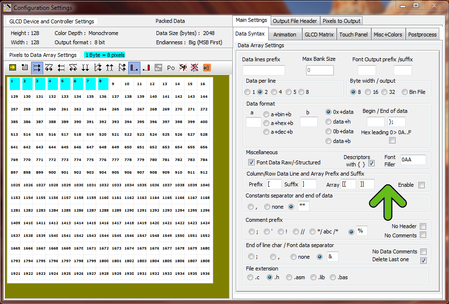
Output of an Array of [ Arrays of  Pixel lines ]

Data of one display line of pixels (direction can be either in colums or in rows) can be separate in a sub array (green arrow)

Example of this kind of data output   (Checkbox enabled must be set )

[[    — Array prefix example

[data for line 1]

[data for line 2]

[data for line n]

]]  — Array suffix example


Bitmap2LCD Configuration Settings Python

Bitmap2LCD File Explorer : Filter Settings

Bitmap2LCD is a tool for programming small Graphic LCDs in embedded systems.

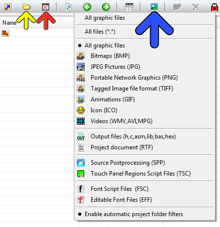
File Explorer : Filter Settings

In the file explorer, you can show/hide the folders in the list (yellow arrow) , Show all files or only the files made today (red arrow) and filter the list by their extension and type (blue arrow) and the panel below the blue arrow.

The filter status can be seen in the file count string which is shown in the statusbar at the right at the top of the window .

Bitmap2LCD Explorer filters

Resize and then Import a graphic into the Work Canvas

Bitmap2LCD is a tool for programming small Graphic LCDs in embedded systems.

Resize and then Import a graphic into the Work Canvas

Bitmap2LCD Resize Preview

Outdated information :

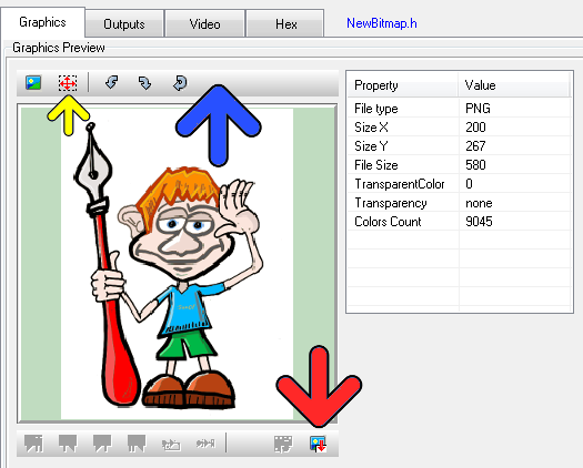
Since v2.6B, there’s a new toolbar at the top of the graphic (blue arrow)

When importing a graphic file, you can choose to resize the graphic size in the graphic preview (yellow arrow) or turn the graphic or reload the original graphic.

If the graphic is much larger in size than the work canvas, you will see a “blue frame” in the preview, frame which shows the size of the Work Canvas. You can move this area to the graphic detail you wish to import. In this case, the later message box resize to fit should be answered with NO.

When you want to resize the graphic, click on the selection button (yellow button) and then define the size on the image with mouse. The preview will be resized.

When ready import the graphic (red arrow) to the floating selection layer above the work canvas. When ready paste the floating selection layer.

Bitmap2LCD : The Configuration Settings Window

Bitmap2LCD is a tool for programming small Graphic LCDs in embedded systems.

OBSOLETE Article : For older versions

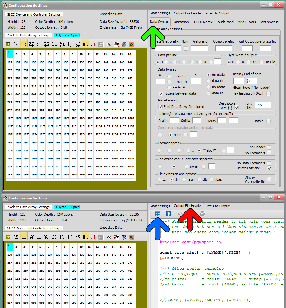
All the configuration settings of the Bitmap2LCD tool have been reorganized and grouped in one single window :

The main settings, the output file header syntax settings, the pixel to data array orientation setting , the optional postprocessing and a new user friendly pixel to data array organisation display.
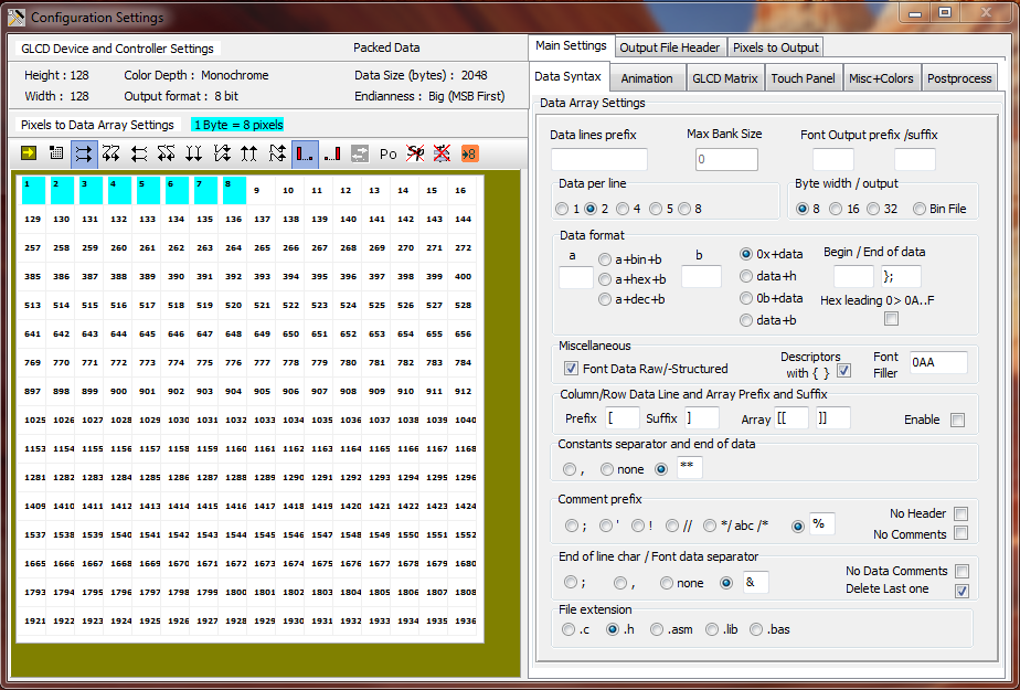
 

Bitmap2LCD Configuration Settings


Let’s see how to configure the GLCD data output settings :

The generated data array file can be configured to meet the syntax requests of your compiler or assembler. There are many possible settings, to make it possible to match the tool with most of the compilers of the market.

At first, you define the table data settings

  • Data Width format. ( 8,16 or 32 bits data)
  • Binary, Hex or decimal format.
  • Syntax of Data Byte/Word (make it compatible with your favorite compiler, assembler)
  • Type of file (extension)


bitmap2lcd output settings


As next, you define the header syntax ( output file header tab)

>>  To edit file header blue arrow )

  • Click on the edit button and the header script is loaded into the editor. Modify it to meet your requirements.
  • When ready, quit the header editor by clicking the same button.
  • Find more about the header syntax at the end of this article.

As next, you define the way the data arrays are arranged to correctly fit in the DDRAM of your LCD controller. ( Data orientation ) These settings must be compatible with the LCD display functions in the GLCD Library you use in your project.

  • The origin corner X0,Y0
  • Data direction (The direction in which the pixels slices are taken from the work canvas and converted to GLCD data, for example in slices or in full canvas height or full canvas width. A slice is 8 pixels in monochrome mode and 2 pixels in 4bpp grayscale mode)
  • The Endianness (Most Significant Bit is first or last)
  • Special settings

More about File Header syntax ( output file header tab )

The script components [&***] can be included only once and will be replaced by the data or value when the data array is generated. Not needed script components can be erased.

[&NAME]

The [$NAME] and the image size and position are optional and can be placed optionally anywhere in the header.

[&SIZE]

Same for Size of Data

[&TRUEORG]

This is the script component if present in the file, to indicate that you want to have the XPOS and YPOS origins of a reduced dynamic table of constants ( a part of the display you want to change ) given from the X0,Y0 corner you selected in the table translation manager window.

[&XPOS]

[&YPOS]

[&WIDTH]

[&HEIGHT]

The corner position on the Work Canvas and the size of the converted graphic area can be exported into the file.

There are additional script components for font generation and data compression.
GLCD Data array output options

Bitmap2LCD is a tool for programming small Graphic LCDs in embedded systems.

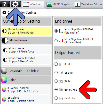
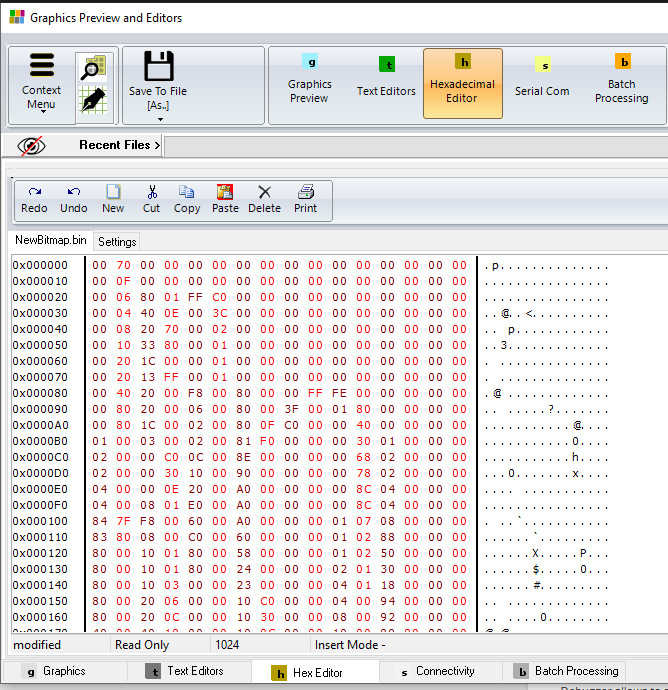
Output of the GLCD data array in a binary file
The converter data output feeds a built in hexadecimal editor and is saved to disk in a binary file (*.hex)

Output of the GLCD data array in a INTEL Hex format

Details about Intel Hex Data Output

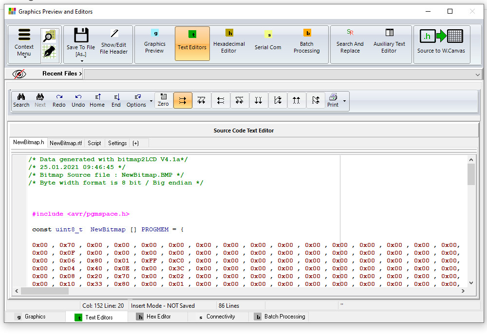
Output of the GLCD data array in a text file for the compiler or assembler, format 8, 16 or 32 bit data

The converter data output feeds a built in text editor and can saved to disk in a text file
( *.c , *.h , *.asm , “.lib etc..)

Next to the data file, a rich text file (*.rtf) which contains all GLCD conversion parameters is written to disk, in the user defined “Documents folder”.

Grayscale GLCD controller support : 4,16 and 32 gray levels

Bitmap2LCD is a tool for programming small Graphic LCDs in embedded systems.

Since V2.3 and upwards, Bitmap2LCD supports the 4,16 and 32 level grayscale controllers. ( Newly implemented are the 4 and 32 gray levels capability )

Color images and pictures can be imported and converted to 4, 16 and 32 gray levels into the work canvas. The software tool then generates the pixel data array in the selected arrangment, 2, 4 or 5 bits per pixel.

Here’s a list of grayscale LCD controllers, featuring 4, 16 and 32 gray levels.


Grayscale LCD Controllers

4 Gray Levels (2bpp)


S6B0741 128×129 Samsung


KS0741 128×129 Samsung


HT1647 64×16 Holtek


ST7541 128×129 Sitronix


ST7571 128×129 Sitronix


ST7586S 384×160 Sitronix


UPD16686 128×128 NEC


UPD16498 128×128 NEC


UPD16488A 128×92 NEC


HD66750 128×128 Hitachi


HD66421 160×100 Hitachi


EM65100 69 x101 Elan Microelectronics Corp


NJU6680 128×128 New Japan Radio


NJU6682 160×132 New Japan Radio


RA8806 320X240 Raio Technology


16 Gray Levels (4bpp)


EM65101 128×160 Elan Microelectronics Corp


SSD1322 480×120 Solomon Systech


SSD1325 128×80 Solomon Systech


SSD1326 256×32 Solomon Systech


SSD1327 128×128 Solomon Systech


32 Gray Levels (5bpp)


ST7529 255×160 Sitronix


GLCD Data Output Settings in Bitmap2LCD

Bitmap2LCD is a tool for programming small Graphic LCDs in embedded systems.

This article is only for releases before V2.5

Let’s look how to configure the GLCD data output settings :

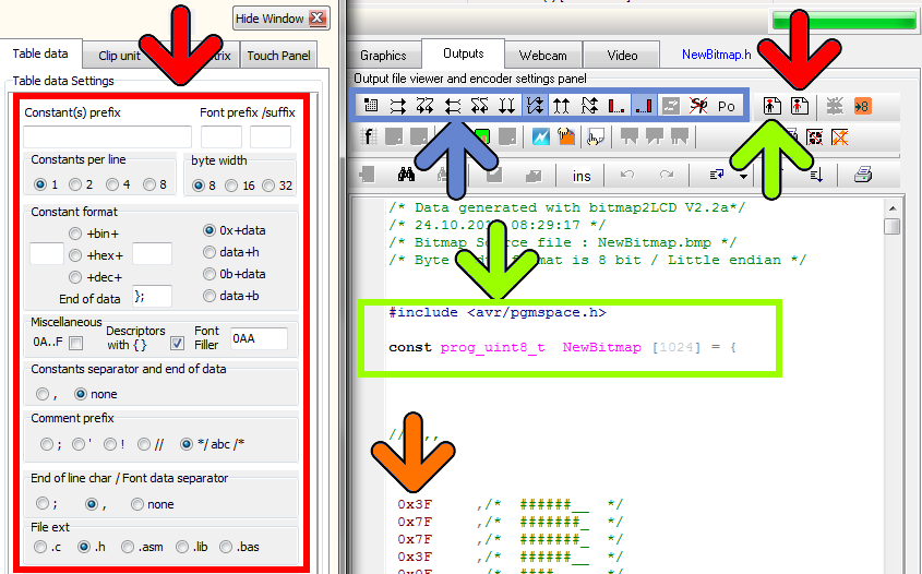
The generated data array file (orange arrow, in the picture below) can be configured to meet the syntax requests of your compiler or assembler. There are many possible settings, to make it possible to match the tool with most of the compilers of the market.

At first, you define the table data settings (red arrow)

  • Data Width format. ( 8,16 or 32 bits data)
  • Binary, Hex or decimal format.
  • Syntax of Data Byte/Word (make it compatible with your favorite compiler, assembler)
  • Type of file (extension)

As next, you define the header syntax (green arrow)

  • Click on the button and the header script is loaded into the editor. Modify it to meet your requirements.
  • When ready, quit the header editor by clicking the same button (green arrow at the right) or the quit button. (script is auto-saved)
  • Find more about the header syntax at the end of this article.


As next, you define the way the data arrays are arranged to correctly fit in the DDRAM of your LCD controller. These settings must be compatible with the LCD display functions in the GLCD Library you use in your project (blue arrow)

  • The origin corner X0,Y0
  • Data direction (The direction in which the pixels slices are taken from the work canvas and converted to GLCD data, for example in slices or in full canvas height or full canvas width. A slice is 8 pixels in monochrome mode and 2 pixels in 4bpp grayscale mode)
  • The Endianness (Most Significant Bit is first or last)
  • Special settings


More about File Header syntax (green arrow)

The script components [&***] can be included only once and will be replaced by the data or value when the data array is generated. Not needed script components can be erased.

[&NAME]

The [$NAME] and the image size and position are optional and can be placed optionally anywhere in the header.

[&SIZE]

Same for Size of Data

[&TRUEORG]

This is the script component if present in the file, to indicate that you want to have the XPOS and YPOS origins of a reduced dynamic table of constants ( a part of the display you want to change ) given from the X0,Y0 corner you selected in the table translation manager window.

[&XPOS]

[&YPOS]

[&WIDTH]

[&HEIGHT]

The corner position on the Work Canvas and the size of the converted graphic area can be exported into the file.

There are additional script components for font generation and data compression.