About GLCD Data Compression

Bitmap2LCD is a tool for programming small Graphic LCDs in embedded systems.

 Update V3.9H

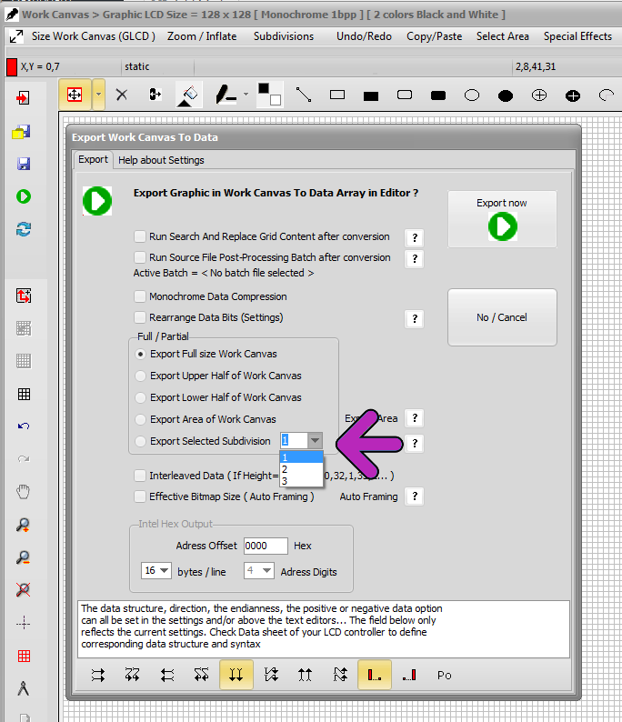
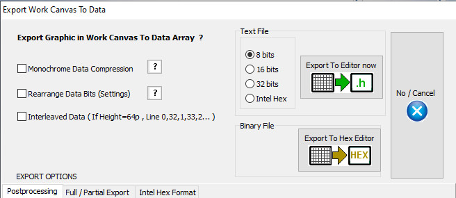
A simple data compression feature, for the output of GLCD data arrays is implemented in Bitmap2LCD

This function is only available for monochrome mode and 8 bit output format.

The 8 bit microcontrollers for price sensitive projects are circuits with often less onchip memory space than most of the 16 or 32 bit devices.

The target is to save as many as microcontroller flash memory as possible. As tables for full display patterns of for example a 128 x 64 dot matrix LCD need 1024 bytes each, the goal of this function was to save flash space for more code or graphics or just to reduce the overall flash capacity and therefore to sink the price of the MCU chip.

The microcontroller firmware has to be able to handle these tables with a special code, which decodes the compressed data. Processing time for decompression has to be allowed.


How does it work ?

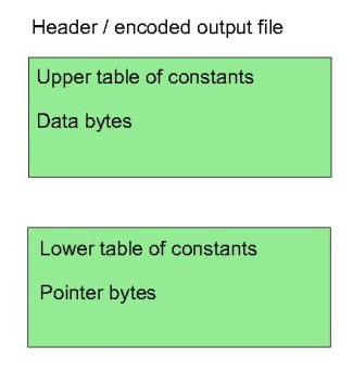
Instead of only converting the black and white pixels found in the work canvas to a linear list of n bytes, with the data compression method explained here, the data array is split into two separate arrays in one single output file : one as usual for the data stream and another for the pointers of each data groups.

Compr1

The basic concept of this compression is based on making groups of consecutive identical data bytes in the data array.


Consecutive identical byte chains, and consecutive different byte chains are handled, the goal here is to save data bytes when a consecutive identical byte chain is found. While the first pointer of a consecutive different bytes chain is a loss of one data byte stored as a pointer, a consecutive identical byte chain of 10 bytes is a win of 8 bytes, the data being written only once in the data array. The count of them is then stored in the pointer byte array part.

The maximum count of consecutive data, identical or different is limited to 127 ( pointer bits 6 to 0 ). If a data count in a group reaches 127, a new group is encoded.

compr2

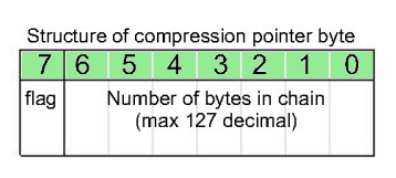
The bit 7 of the pointer byte is the flag for the compression decoder. A 1 (high) is for a chain of identical data bytes, and a 0 (low) is for an chain of different data.


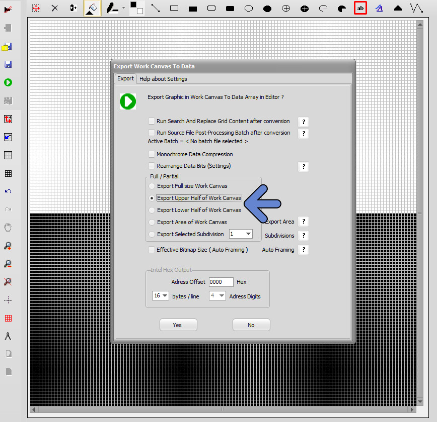
When data compression is active, Bitmap2LCD converts all data and shows the compression rate in the compression statistics at the end of the output file.


This method of compression shows different results in vertical or horizontal orientation conversion, it depends of the LCD graphic !

If possible, before to choose the LCD controller and its specific data orientation in Display RAM , you could try both orientations and compare the possible compression ratios.


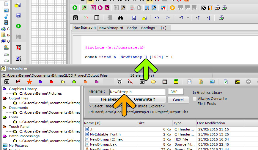
In the Header Include file, the example script below shows how to setup the compression table information.

( It is an example for a GNU-C compiler for ATMEL AVR family )

Everything after the tag [&COMPRESSION] is a script information for the data compression function.

The tag [&CNAME] is replaced in the output table name, by the data array name

with an additional suffix _x ( For example : Newfile_x )

The tag [&CSIZE] is not used yet (v2.3)

In the Header Include file :

[&COMPRESSION]
const prog_uint8_t [&CNAME][&CSIZE] = {

 Please also check the online forum for other topics about this function

Compression Decoder Example

The below example of a function in C language, decodes compressed data arrays converted with bitmap2LCD.

It is for an Atmel AVR target MCU with GCC compiler, a T6963C LCD controller ( horizontal byte orientation from left to right )
No buffer RAM.

Note : For LCD module widths greater than 255 dots, x and width variables should be long integers


// T6963 function for uncompressed bitmaps
 
void GLCD_Bitmap(unsigned char *bitmap, unsigned char x, unsigned char y, unsigned char width, unsigned char height)
{
unsigned char val;
uint8_t LcdX,LcdY,EndX,EndY;
long ip = 0; // table byte counter
LcdX=x; // LCD dot adress X
LcdY=y; // LCD dot adress Y
EndY=y+height-1;
EndX=x+width;
 
while (LcdY < EndY || LcdX < EndX)
{
GLCD_GraphicGoTo(LcdX, LcdY);
GLCD_WriteDisplayData(pgm_read_byte(bitmap + ip));
ip ++;
LcdX=LcdX+8;
if (( LcdX == EndX ) && ( LcdY<EndY ))
{
LcdY++;
LcdX=x;
}
}
 
}
 
 
// T6963 function for Bitmap2LCD compressed bitmaps
 
void GLCD_xBitmap(unsigned char *bitmap, unsigned char *pointer, unsigned char x, unsigned char y, unsigned char width, unsigned char height)
{
 
unsigned char val;
uint8_t p,pv,nb,LcdX,LcdY,EndX,EndY;
long ip = 0; // table byte counter
p = 0; // pointer
LcdX=x; // LCD dot adress X
LcdY=y; // LCD dot adress Y
EndY=y+height-1; // End pixel in Y
EndX=x+width; // End Pixel in X
 
while (LcdY < EndY || LcdX < EndX)
 
{
pv = (int)(pgm_read_byte(pointer + p)); // read the pointer byte
p++;
 
if (pv > 128) // bit 7 is logical high when identical bytes chain, low when different
{
val = pgm_read_byte(bitmap + ip);
ip++;
nb = pv – 128;
 
while ( nb > 0 ) // substract bit 7 value for number of bytes in chain
{
GLCD_GraphicGoTo(LcdX, LcdY); // bytes in chain are identical
GLCD_WriteDisplayData(val);
LcdX=LcdX+8;
nb–;
if (( LcdX == EndX ) && ( LcdY<EndY ))
{
LcdY++;
LcdX =x;
}
}
}
else // bytes in chain are different
{
while ( pv > 0 )
{
GLCD_GraphicGoTo(LcdX, LcdY);
GLCD_WriteDisplayData(pgm_read_byte(bitmap + ip));
ip ++;
LcdX=LcdX+8;
pv–;
if (( LcdX == EndX ) && ( LcdY<EndY ))
{
LcdY++;
LcdX=x;
}
}
}
}
}


Bitmap2LCD Stretching the Chars of a Font

Bitmap2LCD is a tool for programming small Graphic LCDs in embedded systems and a programmable graphic and text processing tool.

Stretching A Font

Update V3.7c

In the Font Panel there is a small Panel for stretching a GLCD Font (blue Arrow) , in width or/and in Height with the possibility to shift the stretched chars along the Y axis.

The “Stretch” checkbox enables or disables the stretching.

This features works when generating a Font, in the font script special mode and when exporting a system font to an editable Font.

bitmap2lcd-stretch-font


Creating a GLCD Animation from scratch with Bitmap2lcd

Creating a GLCD Animation from scratch with Bitmap2lcd

Bitmap2LCD is a tool for programming small Graphic LCDs in embedded systems.

Also read this article !

Let’s see how we can create an animation for small Graphic LCD ( Version 3.7C+ )

bitmap2lcd-animation-menu

  • When in static mode , go to the animation tab and click the Enter Animation button anim  The same button or the Special Mode Exit exiz Button should later be used to exit from the animation mode back to the static mode. An animation will be saved as a standard GIF file.

 Read more about GIF Format

  •  When entered in animation mode, the canvas outline becomes dark gray (green arrow) sub-menu becomes accessible (red arrow) . The animation is a sequence built of frames. The “ghost image” of the previous frame can optionally be displayed, it is a visual help for correct placement of graphic items,
  • bitmap2lcd-animation-mode_1
  • At the top you can read the number of the current frame  (2)  and the number of total frames in the animation (/2) (blue  arrow)
  • In the animation menu , you can use the navigation buttons to move from a frames to another, move to the beginning or the end of the animation. You can play and stop the animation sequence. (orange arrow) An alternative is to use the page-up and page-down keyboard keys to move through the animation frames.
  • Addition of a new animation frame, copying current frame to then next new frame , deleting a frame as well as other animation management functions are located in the animation menu and at the right side of the work canvas (red arrow)

Bitmap2lcd Animation_3

  •  When the animation is done you can convert the frames in GLCD data in one go Start  (green arrow)
  • With this animation made of 5 frames example, Bitmap2LCD produces 6 files : A clip unit file  (the code in the editor) and the 3 frames as data files  (orange  arrow)
  • You can navigate and view these files with the next and previous buttons  (red arrow)
  • Only selected part of the animation frames can be converted : Enable Display Paging Scheme Limits and then select the area to convert. Click conversion button to start data export as usual (green arrow)

Bitmap2lcd Animation_4


  •  In this example, 5 full frame size of data for  a 128 x 128 pixel GLCD are converted (black arrow). If the “Auto-framing” option has been enabled in the configuration settings, an automatic framing of only the area of the changing pixels is made. Then the X and Y positions, the height and the width of the frame is reported inside the clip unit.
  • In the configuration settings window toolAnim , find other animation settings on the “clip unit” panel.
  • In the monochromatic mode, in addition to then auto-framing, an animation output can optionally be “internally compressed” to generate reduced code size. ( read articles in the blog category GLCD Data compression )


GLCD Font Output formats : Raw or Struct

Bitmap2LCD is a tool for programming small Graphic LCDs in embedded systems.

GLCD Font Output formats : Raw or Struct

Standard Edition, Update V3.7c

From release V2.4d , you can choose between two types of font data output, bitmaps in a raw data array or a C tfont structure

Check (raw) or uncheck (struct) the raw/-struct checkbox in the configuration settings panel

Version 3.7 +

bitmap2lcd-font-data-structure

C language tfont structure in stuct font output mode :

typedef struct {
long int code;
const tImage *image;
} tChar;
typedef struct {
int length;
const tChar *chars;
} tFont;


Previous Versions :

Version 3.0 +

Bitmap2lcd Font Settings


Before Version 3.0 +

Bitmap2LCD Configuration Settings Raw Struct


Text Processing Automation Tool

Bitmap2LCD is a tool for programming small Graphic LCDs in embedded systems and a programmable text processing tool.

Text Processing Automation Tool

( Function described here was updated from Bitmap2LCD V2.8a  , and is available with the Standard Edition license )

One of the various features included in the bitmap2LCD GLCD toolbox is the Source Code / Text file processing.

To find and replace text in many files or if it is needed to search and replace different data 100+ times at once, or to proceed to many other text processing tasks , the Bitmap2LCD tool will help you saving precious time to search and replace text in the blink of an eye.

You can program batch scripts of your repetitive text-processing tasks such as auto-replacement or/and auto-insertion of any text in your source code, save it to the disk (.SPP) and define it as the current active batch of a project.

The list of functions in the batch script makes it possible to search automatically for text strings within the code and based on the paired actions, decide whether the alternative text string shall overwrite the text string searched for, or be placed after it.

 Here’s the list of the functions available in the bitmap2LCD text processing tool

( Note : Addition of new functions in the future , also see blue arrow below in fig1. )

List of the conditions and modal switches

if ‘text’

if not ‘text’

while ‘text’

if line number(index)

if last line

if flag

if not flag

and ‘text’

and flag

and not ‘text’

and not flag

or ‘text’

or flag

or not ‘text’

or not flag

begin of loop

end of loop

search back from line end

search from line begin

case sensitive on

case sensitive off

..

List of the functions

then set flag

then reset flag

then insert (index)’text’

then overwrite (index)’text’

then remove ‘text’

then delete until ‘text’

then get integer (index)

then get hex (index)

then get float (index)

then insert integer (index)

then insert hex (index)

then insert float (index)

then next line

then delete line

then insert line

then save as ‘file’

then start copy

then stop copy

then start delete

then stop delete

then save copy as ‘file’

then load and insert ‘file’

etc..

To program a batch , click Edit Current Batch or click New batch ( buttons are located in the main menu )

bitmap2lcd-batch-processing-menu

bitmap2lcd-batch-processing_3

fig. 1

Then choose the conditional function in the Function combo box (blue arrow)

You can’t directly edit the text itself in the editor, but you can move the green cursor up and down in the program (orange arrow) and edit the index , text and comment fields of the line selected by the cursor, in the fields at the top of the editor (green arrow).

Note that the index field can be left at ‘index’ when the cursor position is not known nor fixed : Index is a numeric field , a cursor position of character or text or if left at ‘index’, it will be the cursor position where the searched ‘text’ was found in the conditional instruction before (‘if’) .

An IF followed by one or more THEN is a pass thru the whole text file loaded in the Text Editor (second tab fig1. ) Please remember that every IF + Then(s) Pair is a new pass from the top to the end of the text file.

In the above examples in fig1. and fig2 , a part of the file is copied in another file named copy3.txt located in the folder defined as output files folder .

bitmap2lcd-batch-processing-menu_2

fig 2.

The Processing batch can be started from the user interface, from a single button (see red arrow) or from a main menu item.

See also the article about the automatic post-processing in this topic.

Export Graphic Picture to Data array – Split Data in two parts in height

Export Graphic to Data array – Split Data in two parts in height

The export of the graphic inside the Work Canvas can be exported in two data arrays. The Height is split into two parts.

This only works in one of the horizontal data direction schemes, see red arrows below.

Bitmap2lcd Splitted GLCD Data Direction

In the export Dialog below, there are two options (blue arrow) to export only the Upper or only the Lower half of the work canvas to a data array. In the example below, Upper half are all white pixels and Lower half are all black pixels.

Bitmap2lcd Splitted GLCD

Once one of the upper half or the lower half data array has been exported, the filename must be manually modified in the dialog for example to Newbitmap_Upper or to Newbitmap_Lower to have two separate files inside the folder for the two GLCD halves.(orange arrow)

The variables names in the files are already different, if it’s an upper or a lower part data array (green arrow)

Bitmap2lcd Splitted GLCD Filename

Work Canvas Subdivisions

Bitmap2LCD is a tool for programming small Graphic LCDs in embedded systems and a programmable graphic and text processing tool.

Work Canvas Subdivisions

Update V3.7c

There’s a feature to split the Work Canvas in fixed parts ( subdivisions ) located in the Work Canvas main menu ( green arrow )

How to Define a Subdivision :

  1. Subdivision Menu item : Open / Create Work Canvas Subdivisions ( green arrow )
  2. Draw an area in the work Canvas with the mouse
  3. Make a Subdivision with the area ( blue arrow )

bitmap2lcd-work-canvas-subdivisions

Note: The subdivisions must fit inside the paging scheme lines , the horizontal or vertical red lines.

bitmap2lcd-work-canvas-subdivisions_2

When all needed subdivisions were defined, quit the subdivision creating mode ( red arrow )

A set of subdivisions is attached to the current project name. They are saved and reloaded automatically.

To delete a Subdivision, select the area in the Work Canvas and press delete.

These Work Canvas Subdivisions can separately be exported to data arrays (see example below)

bitmap2lcd-work-canvas-subdivisions_3


Import a Unicode Character into Work Canvas

Bitmap2LCD is a tool for programming small Graphic LCDs in embedded systems.

Import a Unicode Character into Work Canvas exportcharw

Update V3.7c

  • Open then Font Panel and select a Unicode Font, here for example Greek
  • Create a text frame and mouse click at top left text location in the work Canvas -> a red frame area appears (see red arrow)
  • Select a char in the Font Panel grid (yellow Arrow) and click the export button exportcharw (black arrow) OR  double-click on the char in the Font Panel grid (yellow Arrow)
  • When finished, move the Text frame to its location , and Paste paste the Text Area with keyboard key Enter or the Paste button.

bitmap2lcd-export-unicode-to-canvas


Bitmap2LCD : Translations of the Tutorials

Bitmap2lcd_Tutorial_Translation

In Google Chrome, you can translate the displayed web page easily (blue arrow)

Install Plugin / Add-on

In FIREFOX , you can install a plugin and translate like this :

Google Translator for Firefox (blue arrow)

or Translator (red arrow)

translation web page in firefox

https://addons.mozilla.org/en-US/firefox/addon/google-translator-for-firefox/

Bitmap2lcd : Dithering and Color Reduction

Dithering and Color Reduction

Bitmap2LCD is a software tool for programming small Graphic LCDs in embedded systems and a programmable text and graphic processing tool.

Update 4.7b

List of Dithering Algorithms in Bitmap2LCD

Conversion of a color image to monochrome with Dithering Algorithms :

Floyd Steinberg, Nearest Color, Stucki, JaNuNi, Steve Arche, Sierra, Burkes.

About Dithering Algorithms

A graphic placed on the FLOATING SELECTION LAYER can be dithered form the main menu item Convert To

The conversion of an imported color graphic to black and white can be started by the DITHERING button (green arrow) :

bitmap2lcd-dithering-conversion

>.<