Author Archives: Bernie

Graphic LCD and International Fonts and Characters

Bitmap2LCD is a tool for programming small Graphic LCDs in embedded systems and a programmable graphic and text processing tool.

International Fonts and Characters

Update V3.7c

Quote :

Unicode is a computing industry standard for the consistent encoding, representation, and handling of text expressed in most of the world’s writing systems. Developed in conjunction with the Universal Character Set standard and published as The Unicode Standard, the latest version of Unicode contains a repertoire of more than 110,000 characters covering 100 scripts and multiple symbol sets. The standard consists of a set of code charts for visual reference, an encoding method and set of standard character encoding, a set of reference data computer files, and a number of related items, such as character properties, rules for normalization, decomposition, collation, rendering, and bidirectional display order (for the correct display of text containing both right-to-left scripts, such as Arabic and Hebrew, and left-to-right scripts).

Source :

https://en.wikipedia.org/wiki/Unicode

The standard is maintained by the Unicode Consortium.

http://www.unicode.org/

// Quote

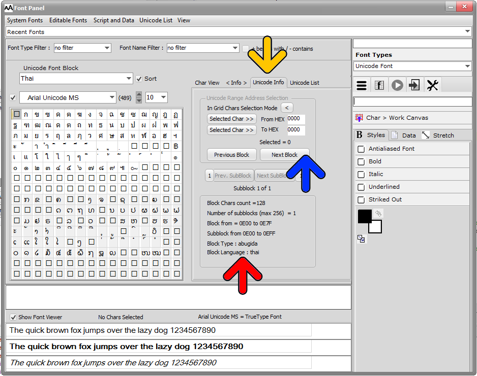
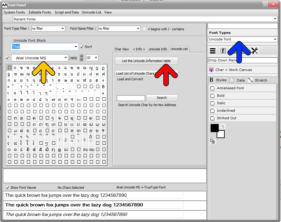
To access the international characters, open the Font panel, select the Unicode fonts (blue arrow)

Select the Font ( for example Arial Unicode MS ) (yellow arrow) and the Unicode Block (in this example Thai )

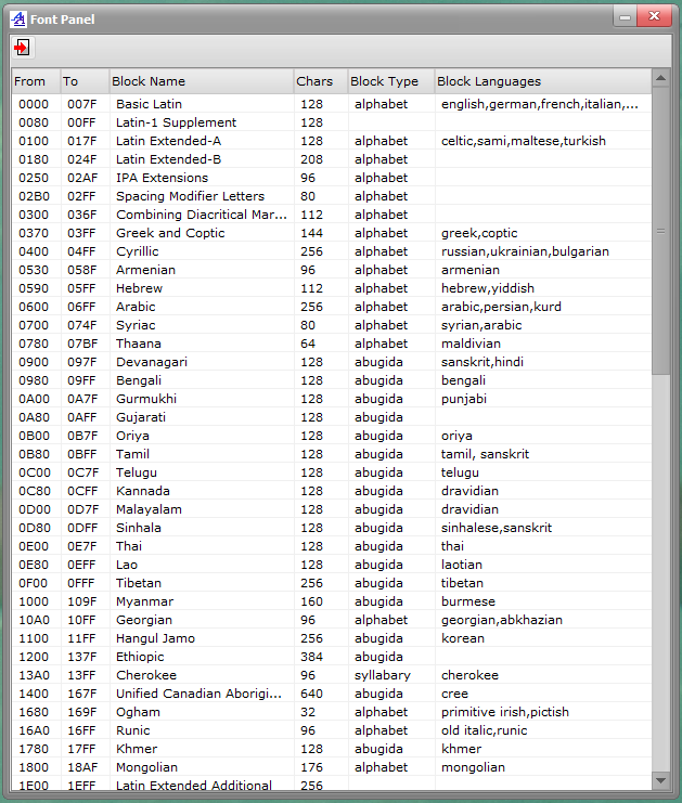
To have an overview of the Unicode block names, addresses, types and language, select the Unicode List tab and click on the List Unicode Information Table button (red arrow)

bitmap2lcd-unicode-information-list


Overview of the Unicode Blocks

Bitmap2lcd Unicode _2


The information of the selected block (red arrow below) are located in the Unicode Info Tab (yellow arrow)

The available information are the number of chars of the selected block, the number of sub-Blocks, if the number of chars exceeds 256 chars ( size of the grid ) , the address range of the chars ( from – To ) , the block type and the block language if specified.

If the number of chars in the block exceeds 256, there are buttons to navigate in the sub-blocks of the block (blue arrow)
bitmap2lcd-unicode-block-info


Re-installing or uninstalling Bitmap2LCD

Bitmap2LCD is a tool for programming small Graphic LCDs in embedded systems.

Re-installing or uninstalling Bitmap2LCD

Up to Version V2.8a (b8) , the folder where your personal tool configuration and all your projects were saved, was’nt automatically deleted when running the uninstall task. This has changed since.

in the Documents folder : see folder Bitmap2LCD inits

If you have an anterior version and want for any reason to uninstall the software, or reinstall it completely, you can just delete this Bitmap2LCD inits folder and all its content.

At next application launch, a new default folder will be created.

You may also find older Bitmap2LCD inits XX-XX-XX folders, if you clicked on “quit and restore factory settings” in the file main menu at some time in the past. ( These folders are just config backups in case you need a configuration recovery )

The Bitmap2LCD Project default project folder in the Documents folder will not be automatically deleted by uninstalling the software.


About the Toshiba T6963C LCD Controller

About the Toshiba T6963C LCD Controller

The Toshiba T6963C graphics controller chip is designed to control small to medium size graphic Liquid Crystal Display modules (LCD). It may be interfaced with a number of different 8-bit micro-processor units (MPU) such as the Z-80 or the 80C51/80C52.

It provides the necessary interface between the MPU and the video RAM (VRAM). It also generates the necessary timing and data signals for the liquid crystal driver circuits. It has a 128 character Character-Generator ROM (CG-ROM) and has the capability to control upto 64K bytes of external display RAM (VRAM). This VRAM may be allocated for text, graphics and external character-generator RAM (i.e. a user definable character generator). The T6963C can support a wide variety of LCD formats and has the ability to combine text and graphics data on to the LCD. A number of character attribute functions are also available.

Main Functions and Features of T6963C

– Simple 8-bit parallel interface
– Hardware Selectable Display Formats: Columns: 32, 40, 64, 80 – Lines: 2, 4, 6, . . . . . 28, 32
– Hardware Selectable Fonts(W) x (H): 5×8, 6×8, 7×8, or 8×8
– Programmable Duty Cycles: 1/16 to 1/128
– Internal 128 character CG-ROM
– Software allocation of Text, Graphic and Character Generator RAM (CG-RAM)
– Ability to mix and merge text with graphics
– Low power CMOS design
– Operates up to 5 MHz

The Aslic AX6963 , The RAIO RA6963 are T6963 compatible LCD controller devices

Bitmap2LCD supports the T6963c 6 bit display mode

Bitmap2lcd : About Work Canvas and Color Depth

Bitmap2LCD is a software tool for programming small Graphic LCDs in embedded systems and a programmable text and graphic processing tool.

About Work Canvas and Color Depth

Update V4.7b

The WORK CANVAS is a monochrome, grayscale or color graphic editor.

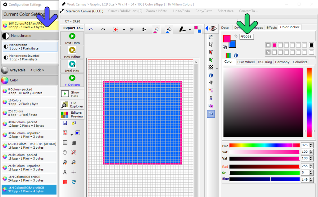
Color Depth of the canvas (number of colors) is selected in the Configuration Settings.

The COLOR PICKER adapts to the color depth setting (blue arrow).

Example : in 4096 colors mode, the picked color will be the nearest color found in the internal default or custom 4096 colors palette. There are color palettes for 8, 16, 256, 4096, 65535, 262k Colors (green arrow).

At import of a color graphic into the WORK CANVAS, a conversion to the defined color depth palette of 8, 16, 256, 4096, 65535 or 262k Colors is performed.

Color Palettes

Default and Custom Color Palettes can be managed in the main menu Color Palette .

>.<

Generating 2bpp grayscale data on two pages

Bitmap2LCD is a tool for programming small Graphic LCDs in embedded systems and a programmable graphic and text processing tool.

Generating 2bpp grayscale data on two pages

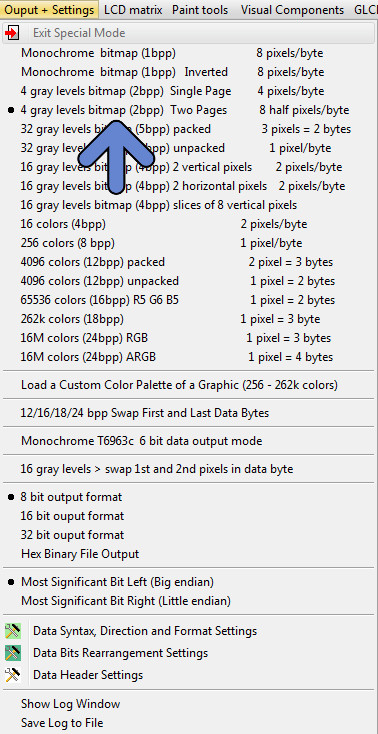
From Version 3.4b, a new setting for an alternative output format for 2bpp grayscale has been implemented.

The data then is generated in two separate data arrays (or pages) : The first page of 1bpp data is to turn on light gray, and the second page of 1bpp data is to turn dark gray.

For example, for a 128 x 96 2bpp gray LCD Panel, the generated data is split in two arrays of 128 x 12 bytes. Each byte contains 1bpp of 8 pixels, combined with the other byte in the other array to make the 2bpp.

Target : For example LCD controller S6B0741 (Samsung)

bitmap2lcd 4bpp grayscale

Bitmap2LCD : Serial Communication

Bitmap2LCD is a tool for programming small Graphic LCDs in embedded systems and a programmable graphic and text processing tool.

Bitmap2LCD : Serial Communication


The target here is to directly connect a serial Graphic LCD on a USB port of the computer using a FTDI chip based USB adaptation module

Visit this Website for modules and and drivers :

http://www.ftdichip.com/Products/Modules/DevelopmentModules.htm

The USB to UART Com option is already working while the RS485, I2C and SPI Serial Interface adapations are currently under development ( begin of 2017 )


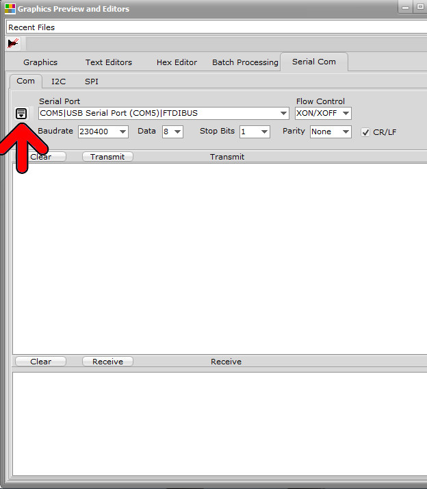
In the same Window as the Text editor and the Hex Editor , there’s also a Serial Communication Tab and Panel. In the local Menu ( red arrow ) you can connect (open) the selected Serial Port.

You can choose the Transmit Only or the Transmit and Receive mode. Remember that the Transmit and Receive mode scans the serial interface for received chars, this loop is computing time consuming. You can close the serial port to stop this loop when not needed.

Bitmap2LCD Serial COM Terminal

You can write data to send in the upper field and start the communication by transmit , and see the received chars in the lower field. You can also transmit the content of the Text editor.

Displaying Dynamic Analog Numbers

Bitmap2LCD is a tool for programming small Graphic LCDs in embedded systems and a programmable graphic and text processing tool.

Displaying Dynamic Analog Numbers or Floating Point Numbers

The panel of parameters to show dynamic numbers is located In the extended part of the Work Canvas (blue arrow)

This feature can be used to simulate LCD panel designs with variable numbers, instead of leaving a blank area where a dynamic number will later be programmatically displayed on the target hardware.

In the Analog Dynamic Value Panel (red arrow) You can define the X and Y coordinates, the Min and Max value, the value to display and choose between several decimal representation options.

The number (green arrow) can be shown / hidden and its value changed using a Trackbar. The Font, font Size and font style can be defined in the Font Panel.


Bitmap2lcd Dynamic Analog Numbers


Code example : Displaying a bitmap on Graphic LCD

Bitmap2LCD is a tool for programming small Graphic LCDs in embedded systems and a programmable graphic and text processing tool.

Code example : Displaying a bitmap on a Graphic LCD

Example for an Atmel AVR Microcontroller + a monochrome 128 x 64 Dot Matrix GLCD + using a KS0108 GLCD Controller Library.


#include <avr/io.h>
#include “C:\Users\BE\GLCD Lib\KS0108.c”
#include “C:\Users\BE\GLCD Lib\KS0108-AVR.c”
#include “C:\Users\BE\Documents\Bitmap2LCD Project\Output Files\NewBitmap.h”
void LoadBitmap(const uint8_t *bitmap)
{
uint8_t i, j;
for(i=0; i<64; i+=8)
for(j=0; j<128; j++)
{
GLCD_GoTo(j, i);
GLCD_WriteData(pgm_read_byte(bitmap++));
}
}
int main(void)
{
while(1)
{
LoadBitmap(NewBitmap);
}
}


Newbitmap.h

The 128 x 64 pixels bitmap converted to data array

#include <avr/pgmspace.h>
 
 const uint8_t  NewBitmap [] = {
 
 0x20 , 0x00 , 0x00 , 0x00 , 0x00 , 0x00 , 0x00 , 0x00 , 0x00 , 0x00 , 0x00 , 0x00 , 0x00 , 0x00 , 0x00 , 0x02,
 0x10 , 0x00 , 0x00 , 0x00 , 0x00 , 0x00 , 0x00 , 0x00 , 0x00 , 0x00 , 0x00 , 0x00 , 0x00 , 0x00 , 0x00 , 0x04,
…  Bitmap 1024 Data bytes in Total
0x80 , 0x00 , 0x00 , 0x00 , 0x00 , 0x00 , 0x00 , 0x00 , 0x00 , 0x00 , 0x00 , 0x00 , 0x00 , 0x00 , 0x00 , 0x00,
 0x00 , 0x00 , 0x00 , 0x00 , 0x00 , 0x00 , 0x00 , 0x00 , 0x00 , 0x00 , 0x00 , 0x00 , 0x00 , 0x00 , 0x00 , 0x00
};