Generating 2bpp grayscale data on two pages

Bitmap2LCD is a tool for programming small Graphic LCDs in embedded systems and a programmable graphic and text processing tool.

Generating 2bpp grayscale data on two pages

From Version 3.4b, a new setting for an alternative output format for 2bpp grayscale has been implemented.

The data then is generated in two separate data arrays (or pages) : The first page of 1bpp data is to turn on light gray, and the second page of 1bpp data is to turn dark gray.

For example, for a 128 x 96 2bpp gray LCD Panel, the generated data is split in two arrays of 128 x 12 bytes. Each byte contains 1bpp of 8 pixels, combined with the other byte in the other array to make the 2bpp.

Target : For example LCD controller S6B0741 (Samsung)

bitmap2lcd 4bpp grayscale

Bitmap2LCD : Serial Communication

Bitmap2LCD is a tool for programming small Graphic LCDs in embedded systems and a programmable graphic and text processing tool.

Bitmap2LCD : Serial Communication


The target here is to directly connect a serial Graphic LCD on a USB port of the computer using a FTDI chip based USB adaptation module

Visit this Website for modules and and drivers :

http://www.ftdichip.com/Products/Modules/DevelopmentModules.htm

The USB to UART Com option is already working while the RS485, I2C and SPI Serial Interface adapations are currently under development ( begin of 2017 )


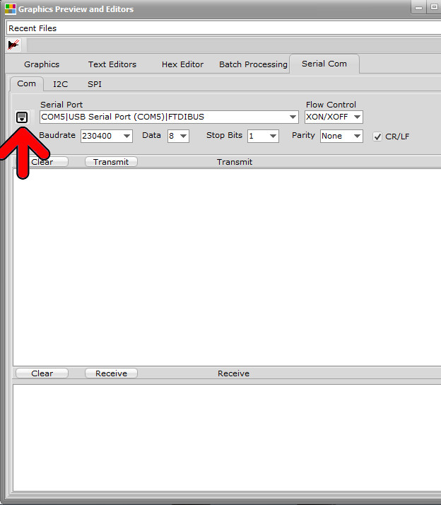
In the same Window as the Text editor and the Hex Editor , there’s also a Serial Communication Tab and Panel. In the local Menu ( red arrow ) you can connect (open) the selected Serial Port.

You can choose the Transmit Only or the Transmit and Receive mode. Remember that the Transmit and Receive mode scans the serial interface for received chars, this loop is computing time consuming. You can close the serial port to stop this loop when not needed.

Bitmap2LCD Serial COM Terminal

You can write data to send in the upper field and start the communication by transmit , and see the received chars in the lower field. You can also transmit the content of the Text editor.

Displaying Dynamic Analog Numbers

Bitmap2LCD is a tool for programming small Graphic LCDs in embedded systems and a programmable graphic and text processing tool.

Displaying Dynamic Analog Numbers or Floating Point Numbers

The panel of parameters to show dynamic numbers is located In the extended part of the Work Canvas (blue arrow)

This feature can be used to simulate LCD panel designs with variable numbers, instead of leaving a blank area where a dynamic number will later be programmatically displayed on the target hardware.

In the Analog Dynamic Value Panel (red arrow) You can define the X and Y coordinates, the Min and Max value, the value to display and choose between several decimal representation options.

The number (green arrow) can be shown / hidden and its value changed using a Trackbar. The Font, font Size and font style can be defined in the Font Panel.


Bitmap2lcd Dynamic Analog Numbers


Code example : Displaying a bitmap on Graphic LCD

Bitmap2LCD is a tool for programming small Graphic LCDs in embedded systems and a programmable graphic and text processing tool.

Code example : Displaying a bitmap on a Graphic LCD

Example for an Atmel AVR Microcontroller + a monochrome 128 x 64 Dot Matrix GLCD + using a KS0108 GLCD Controller Library.


#include <avr/io.h>
#include “C:\Users\BE\GLCD Lib\KS0108.c”
#include “C:\Users\BE\GLCD Lib\KS0108-AVR.c”
#include “C:\Users\BE\Documents\Bitmap2LCD Project\Output Files\NewBitmap.h”
void LoadBitmap(const uint8_t *bitmap)
{
uint8_t i, j;
for(i=0; i<64; i+=8)
for(j=0; j<128; j++)
{
GLCD_GoTo(j, i);
GLCD_WriteData(pgm_read_byte(bitmap++));
}
}
int main(void)
{
while(1)
{
LoadBitmap(NewBitmap);
}
}


Newbitmap.h

The 128 x 64 pixels bitmap converted to data array

#include <avr/pgmspace.h>
 
 const uint8_t  NewBitmap [] = {
 
 0x20 , 0x00 , 0x00 , 0x00 , 0x00 , 0x00 , 0x00 , 0x00 , 0x00 , 0x00 , 0x00 , 0x00 , 0x00 , 0x00 , 0x00 , 0x02,
 0x10 , 0x00 , 0x00 , 0x00 , 0x00 , 0x00 , 0x00 , 0x00 , 0x00 , 0x00 , 0x00 , 0x00 , 0x00 , 0x00 , 0x00 , 0x04,
…  Bitmap 1024 Data bytes in Total
0x80 , 0x00 , 0x00 , 0x00 , 0x00 , 0x00 , 0x00 , 0x00 , 0x00 , 0x00 , 0x00 , 0x00 , 0x00 , 0x00 , 0x00 , 0x00,
 0x00 , 0x00 , 0x00 , 0x00 , 0x00 , 0x00 , 0x00 , 0x00 , 0x00 , 0x00 , 0x00 , 0x00 , 0x00 , 0x00 , 0x00 , 0x00
};


How to use bitmap2LCD ? A Short Tutorial

Welcome to Bitmap2LCD  !

You can find various TUTORIALS on-line on the Bitmap2LCD BLOG.

https://bitmap2lcd.com/blog

The HELP topics are also easily accessible from inside the

 tool, using the internal Web Browser.


Presentation of Bitmap2LCD (Youtube)


Link for versions anterior to V3.7


Getting Started : A short tutorial

Bitmap2LCD is a software tool for programming small Graphic LCDs in embedded systems and a programmable text and graphic processing tool.


How to find information here ?

At the TOP RIGHT HAND SIDE of this BLOG you will find

For example the link (green arrow) of this Quick Tutorial
You also can search this website using keywords (orange arrow)
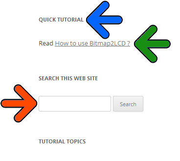
Bitmap2lcd Blog Search

and you can browse the listed topics

Translation of these Tutorials 

Translations  Traductions  Übersetzungen  Traducciones_ Traduzione 


Find Help and Tutorial using the Internal Web Browser

Use the Topic Menu Item as shown below
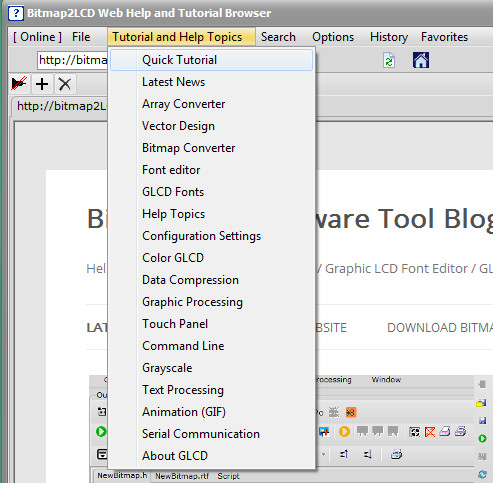
 

bitmap2lcd Web Browser

Fig 1 ) 

Already have discovered the presentation slide show on the website  ?

It’s the same sideshow as the one included in the demo/trial version of the software tool. A general info about what this is it all about.

Link to the Slideshow


The Windows

The red frame  below shows where, in the Main+Windows tab of the Main Menu, to open and show the different Windows of the Program

bitmap2lcd-windows

fig 2 )

Bitmap2LCD is a multi-window application and supports dual screen.

List of the windows : Main window, LCD Viewer, Configuration Settings, File explorer, Graphic and Editors Window, Tool menu, Work Canvas, Adjustments, Font Panel and internal Web Browser.

You can show or hide (minimize) the windows, move them to the secondary monitor.


.

.

Getting Started  > Basic Settings

GETTING STARTED > BASIC SETTINGS

.

.

The Work Canvas

It’s the GRAPHIC EDITOR, the paintbox , You can draw pixels and shapes, import graphics into it. It has a user defined “color depth” which is the same as the target GLCD of the project.
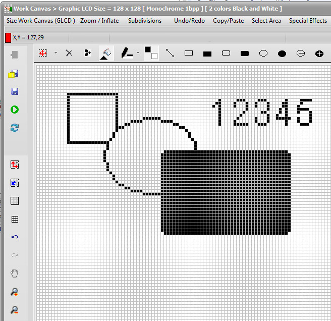
bitmap2lcd-work-canvas

Fig 3 )

The Color Depth of the Work Canvas

Monochrome , Grayscale or Colors
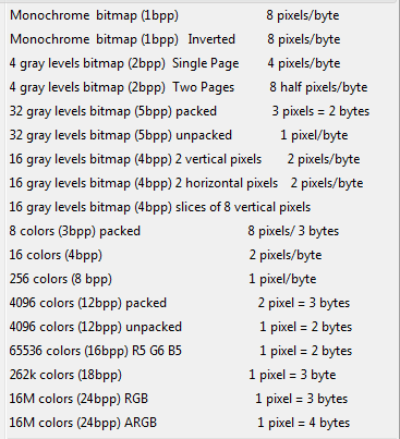
Bitmap2lcd Color depth

Fig 4 )

Details about the Work Canvas

Details about Grayscale


Load a graphic

LOADING A GRAPHIC USING A STANDARD WINDOWS DIALOG OR LOADING IT FIRST INTO PREVIEW ? 

  • You can either use the Load Graphic Dialog ( red frame )

bitmap2lcd-load-graphic

Fig 5 )

OR

  • open / switch to the FILE EXPLORER
  • In the list of files, click to select your particular graphic file you want to load (fig6 blue arrow) , it appears in the GRAPHICS PREVIEW window at the right side.
  • Resize or turn/tilt the preview image using the buttons located at the top of the GRAPHIC PREVIEW.
  • Double click in the graphics viewer (yellow arrow) or the click the import button located at the top or bottom of the preview (fig6. Green arrow)
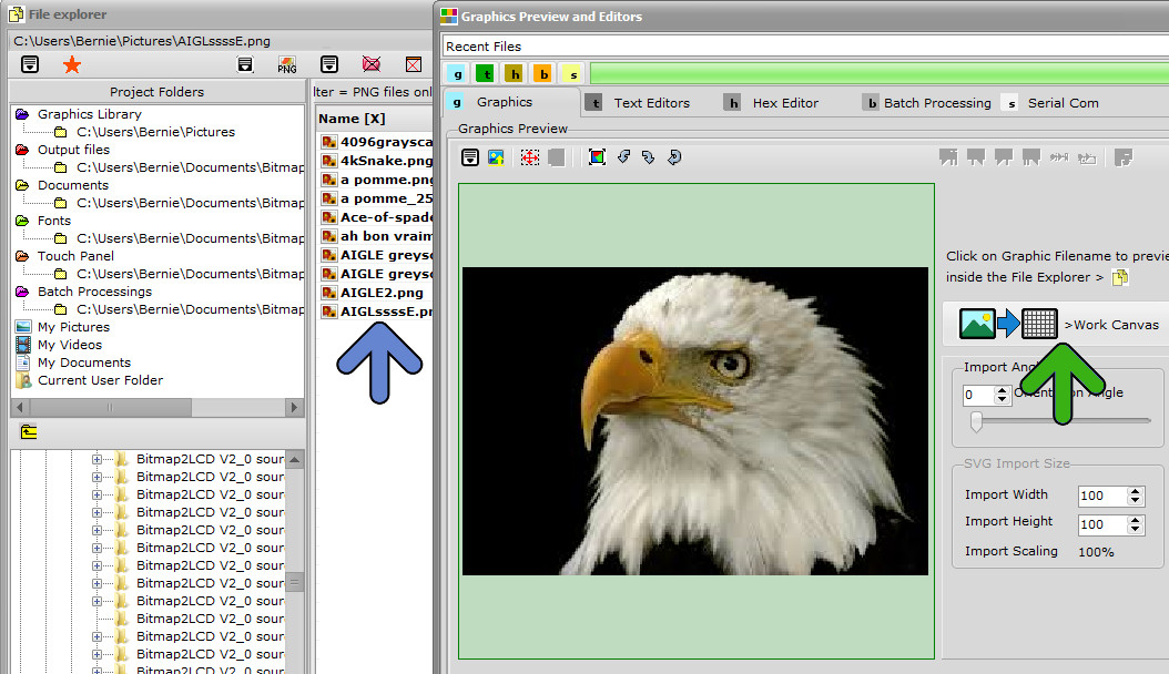
bitmap2lcd-load-graphic-preview

fig 6). File explorer view

If the graphic is larger than the WORK CANVAS a message box will ask you if you want resize the image to fit the canvas or not.

The Floating Selection Layer

MOVING THE GRAPHIC IMPORTED INSIDE THE FLOATING SELECTION LAYER ? 

The graphic will be imported in the FLOATING SELECTION LAYER not directly into the WORK CANVAS (fig7. imagine your own graphic inside the canvas)

The red frame (fig7. red arrow) around the canvas means that you will have to PASTE paste the graphic into the canvas after MOVING it, convert it. When outline frame is red, it means that a “floating ” SELECTION LAYER above the canvas is displayed…

The imported graphic can be moved around above the Work canvas : Move/drag the red frame to the desired canvas location with the left mouse button pressed. (fig7. blue arrows)

Then PASTE paste the FLOATING SELECTION LAYER (fig7. green arrow) The red frame in the frame and around the work canvas disappears. (There are also other ways to Paste, in menus, using the return key etc..)
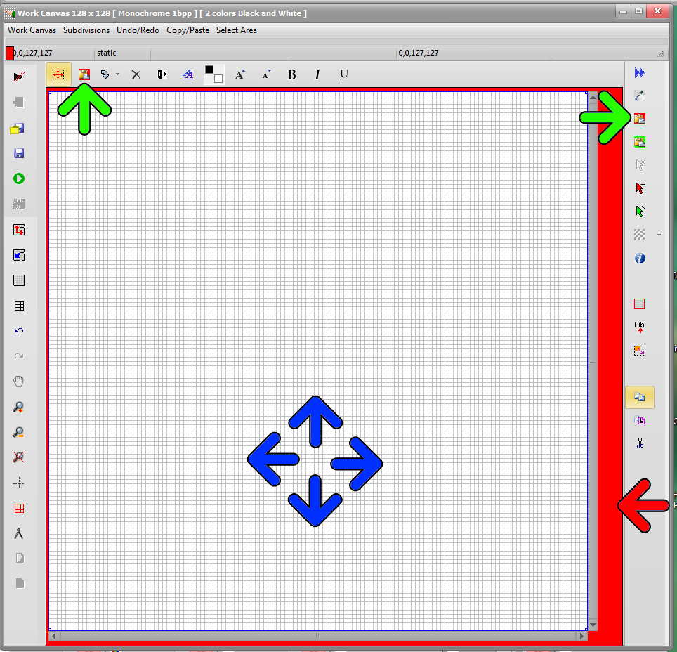
bitmap2lcd selection layer

fig 7 ) Import a graphic file

.

Converting a bitmap to Monochrome

THRESHOLD LEVEL OR DITHERING ?

If you’re loading a COLOR graphic file to convert to black and white for MONOCHROME GLCDs you have the choice of applying a Black and White THRESHOLD level (red arrow), or applying a DITHERING (green arrow) with monochrome color reduction.

Dithering Parameters are located in the main menu of this Window

When the conversion to Black and white is finished, PASTE the floating SELECTION LAYER (Blue Arrow) to the WORK CANVAS

Details about dithering
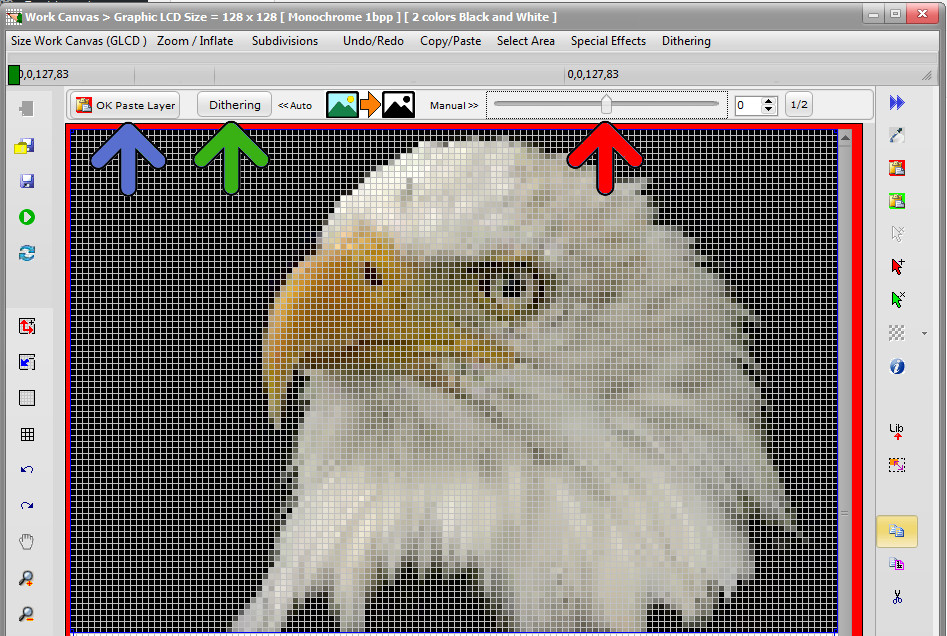
bitmap2lcd-convert-to-black-and-white-dithering

Fig 8 )

Converting a bitmap to GLCD data.

Start   Export WORK CANVAS Graphic To a DATA ARRAY inside the Text Editor

Start HEX   Export WORK CANVAS graphic to Data inside the HEX Editor / BINARY file

Start Selected Export a selected area of the WORK CANVAS To a Data Array inside the TEXT EDITOR
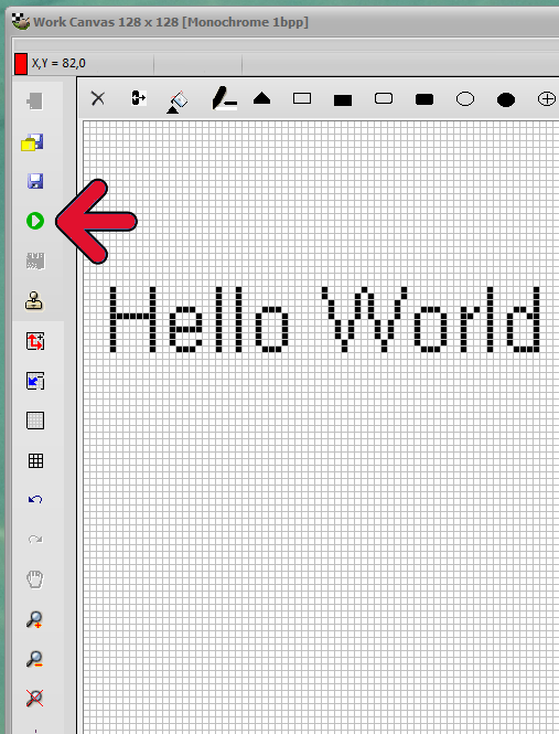
Bitmap2lcd export graphic

Fig 9 )

Start a Graphic To Data conversion (fig 9. red arrow)

Your hexadecimal file appears in the Text editor, formatted according to the defined configuration settings. (fig 10)
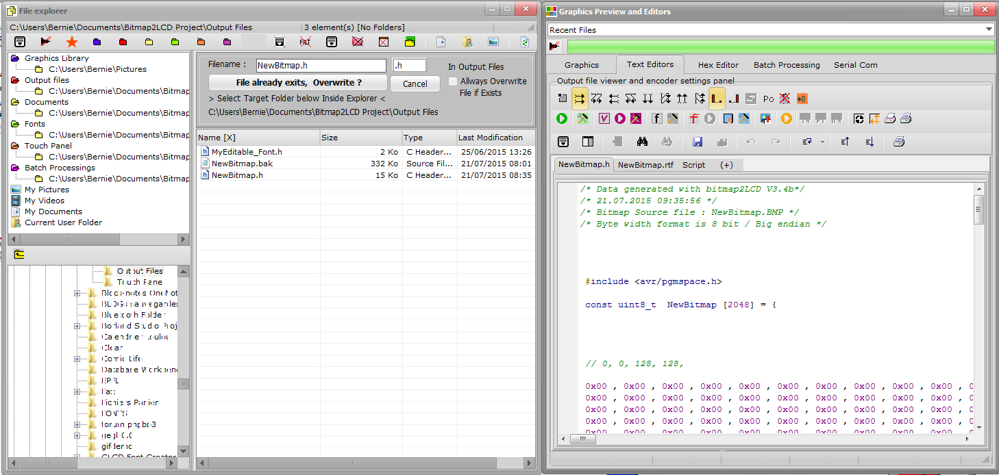
bitmap2lcd output file

Fig 10) Bitmap has been converted to the Hexadecimal, decimal or binary  file in the text editor.


Basic Configuration

Where to find and change the SETTINGS

Link to Basic Configuration

Example Of How to Convert A graphic To a Data Array

Example of how to convert a Graphic to a Array of Data

.

System font, Editable Font, Anti-aliased Font, GLCD Font  with Bitmap2LCD

Info about Fonts in Bitmap2LCD

.

Projects, Artworks and Filenames

A PROJECT is a set of configuration settings ( There are many possible settings ! )

If you work on different GLCD projects, you can save the “current” settings inside a Project name. It’s the easiest and fastest way to switch from one to another.

A so called “Artwork” is a set of files related to the graphic source filename : In the below example a graphic saved for example as NewBitmap.BMP , will be converted to an output file called NewBitmap.h , and the associated touch panel file will then be named NewBitmap.TSC (Red Arrow)  

When you save your Artwork with”Define Artwork Name”  in the GLCD Graphic Tab (Red Frames), as a bitmap,  you will change the basic filenames

bitmap2lcd-artwork-name

Fig 11 )

Color picker

Bitmap2LCD has built in functions which are very similar to the popular MS Paint program

You can select the foreground (PEN COLOR) and background colors (BRUSH COLOR) for painting and WRITING text by clicking in the color boxes of the menu window.

You can copy foreground color to background colors or swap them when clicking in the small boxes around the colors boxes.
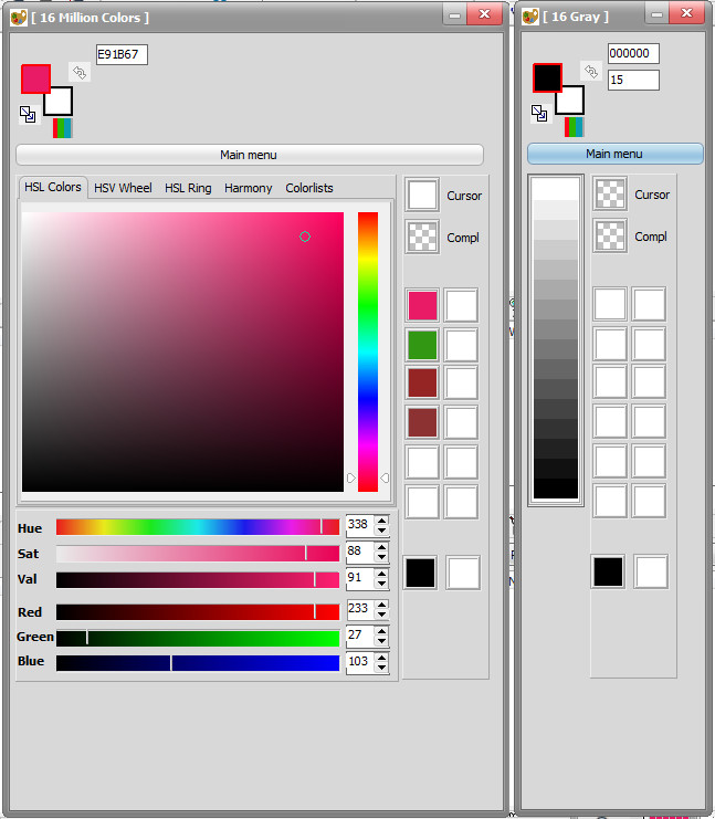
bitmap2lcd Color PickerFig 12 ) The Color Picker ( Here the Color mode Picker and the 16 gray shades mode picker )


Drawing tools

Buttons are located At the top of the Work Canvas
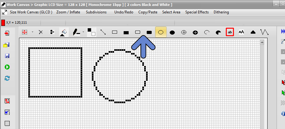
bitmap2lcd-drwaing-toolsFig 13) drawing tools


Write a text

Button is located at the top of the Work Canvas (blue arrow)

bitmap2lcd-write-text

Fig 14 )

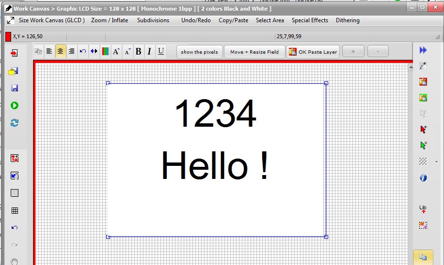
There are 2 different ways to write text inside the work canvas :

  • The Text Field Editor
  • The single Line Text editor

bitmap2lcd-write-text_2

Fig 15 )

Example of using the single Line Text Editor, text can be moved and pasted with paste


bitmap2lcd-field-text-editor

Fig 16 )

Example of using the Text Field Editor, text can be moved and pasted with paste


Working in Vector Mode (GLCD Library)

Using GLCD library functions like GLCD.rect(x,y,h,w) or GLCD.GotoXY(x,y) and similar :

Please follow this link :

Vector Mode

Target Code Example : Displaying a bitmap on an

Atmel AVR MCU

Code example

.

Software Updates

With Standard Edition of Bitmap2LCD, you get unlimited Software Updates

Details About Software Updates

Bitmap2LCD development and Support

A feature you would like to see implemented not yet available ?

submit us your Idea !  Need support  ? Contact us !


An Explanation of LCD Viewing Angle

An Explanation of LCD Viewing Angle

Definition of Bias angle & Viewing angle:

Since LCDs have limited viewing angles, they tend to lose contrast and become hard to read at some viewing angles. Generally the size of the viewing angle is determined by several factors primarily the type of Liquid Crystal fluid and the duty cycle. Because the viewing angle tends to be smaller than most people would like, a bias is designed into the module at the time of manufacturing.
This means the nominal viewing angle is offset from the perpendicular by some amount. Therefore; several LCD versions are offered with this bias set to different angles or positions to accommodate as many applications as possible. The termBias angle is often used erroneously with the term Viewing angle..
The Bias angle is the angle fromthe perpendicular fromwhich the display is best viewed.
This angle is determined when the display is designed and can be set at any angle or orientation.
The orientation of the Bias angle of a LCDdisplay is often stated with reference to a clock face.
If the offset is above the display, it is referred to as a 12:00 or Topview.

The View angle isthe angle formed on either side of the Bias angle, where the contrast of the display is still considered acceptable. Generally, this contrast is specified as 1.4:1. A typical STN character display running at a duty cycle of 1/16 has a viewing angle of ±20 degrees and a bias angle of 25 degrees.
For example, assume the display is a 12:00 (top view) type. When the display is viewed from 25 degrees above the vertical, it will be at its maximumcontrast and best look. If the viewer moves their eyes further above the display by an additional 30 degrees, theywill see a contrast reduction, but the display will still be readable.

Moving the view position any further above the display will reduce the contrast to an unacceptable degree.

Source PDF =>http://www.newhavendisplay.com/app_notes/LCD_Viewing_Angles.pdf


The LCD Glossary

The LCD Glossary

1/4 VGA
Resolution of 320 x 240 dotsCCT
Cold Cathode Tube

C/F
Color Filter

COF
Chip-on-Flex

COB
Chip-on-Board

COG
Chip-on-Glass

CR
Contrast Ratio

DBEF
Dual Brightness Enhancement Film

DSM
Dynamic Scattering Mode

DSTN
Double Super-Twisted Nematic

EL
Electroluminescent Light

FEM
Field Emissive Mode

FSTN
Film Super-Twisted Nematic

HTN
High Quality Twisted Nematic

ISTN
Improved Super-Twisted Nematic

ITO
Indium Tin Oxide

LCD
Liquid Crystal Display

LCDP
Liquid Crystal Display Panel

LED
Light Emitting Diode

MLA
Multi-Line Addressing

MTN
Modulated TN

PLCD
Plastic Liquid Crystal Display

RGA
Returned Goods Authorization

SRC
Super Reflective Color (Birefringent Color)

STN
Super-Twisted Nematic

TAB
Tape Automated Bonding

TCRF
Temperature Compensation Retardation Film

TC-STN
Temperature Compensation Super-Twisted Nematic

TDF
Transflective Display Film

TFT
Thin Film Transistor

TN
Twisted Nematic

VGA
Resolution of 640 x 480 dots

VHC
Very High Contrast (Technology used for Static or duty automotive
products with CR 1000:1)

WTN
Wide Viewing Twisted Nematic

WVF
Wide Viewing Film

Source : Optrex Website

About Touch screen / Touch panel

About Touch screen / Touch panel

:: General Informations collected on the Internet , moved from the bitmap2lcd forum ::


4-WIRE ANALOG RESISTIVE TOUCH SCREEN

The active layers of a 4-wire type touch screen consist of a partially conductive (resistive) coating applied uniformly to the panel. Conductive bus bars are screened with silver ink across opposing edges of the panel.

The ridged and flexible panels are mounted with the bus bars perpendicular to each other.

Measurements are made by applying a voltage gradient across one of the layers and measuring the voltage on the other layer. This measurement is made twice, once with the
gradient across the ridged layer and the measurement taken from the flexible layer and again with the gradient applied to the flexible layer and the measurement taken from the ridged layer.

The gradient is usually produced by grounding one bus bar and applying +5v to the other bus bar. This will produce a smooth voltage gradient in one axis across the panel.

With a 4-wire touch screen two separate setups and measurements are required, one in the X-axis (left-right) and one in the Y-axis (up-down) to define the touch point. Figure 2
illustrates the setup for making the two measurements. The actual switching of the 4 touch screen connections is done using an array of low on-resistance FET transistors and the
voltage measurements are made with an A/D converter. The host micro controller controls both these elements. When a layer is being used as a sens layer all other connections to
that layer must be left floating.
The resistance of the bus bars and the connection circuitry introduces an error (offset) in the voltage measurements.
These offsets can also drift with changes in temperature, humidity and time. If the touch screen is to be used only with a finger the offsets will constitute a small percentage of the voltage represented by the large size of the finger and can be ignored. If, however, the touch screen is to be used with a stylus for drawing or signature capture then these offsets should be taken into account. This can be done by calibrating the screen periodically or by utilizing an 8-wire touch screen.

8-WIRE ANALOG RESISTIVE TOUCH SCREEN

8-wire touch screens compensate for drift by adding 4 additional reference lines. This allows the voltage to be measured directly at the touch screen bus bars. Note: you can use an 8-wire touch screen in 4-wire mode by connecting the drive and reference lines together. Use of this type of touch screen won’t eliminate the need for an initial calibration of the touch screen but should eliminate the need for any subsequent calibrations.

The simplest way to connect an 8- wire touch screen and take advantage of its benefits is to use a ratio-metric A/D converter supplying the reference voltages fromthe touch screen directly into the references of the A/D converter.

5-WIRE ANALOG RESISTIVE TOUCH SCREEN

The 5-wire touch screen differs from the 4-wire type mainly layer, the ridged layer, while the other layer is the sense for making the measurements.

The sequence of events during the measurements is this. The voltage gradient is set up on the x-axis and a voltage measurement is taken from the sens layer.

The voltage gradient is then switched to the y-axis and another voltage measurement is taken from the same sense layer.

Hantronix Source Application Note

PDF => A Hantronix application note about analog touch screens

List of touch screen controller integrated circuitsTexas intruments / Burr Brown

TSC2000 / TSC2003 / TSC2005 / TSC2046
ADS7846
ADS7843

Maxim

MAX11801 / MAX11801 / MAX11803
MAX11810 / MAX11811
MAX1233 / MAX1234
MAX7843 / MAX7846
MXB7843 / MXB7846

ST Microelectronics

STMPE811

Atmel

AT42QT4120 / AT42QT4160

National Semiconductors

LM8300 / LM8500

DMC

TSC-40

Microchip

AR 1000 / AR1010 / AR1020

PDF==>
4 and 5W touch screen Application note from Atmel


About GLCD Contrast

About GLCD Contrast

:: General Informations collected on the Internet , moved from the bitmap2lcd forum ::

Application note about LCD contrast Control  >> PDF =>About LCD contrast Control

More about Negative Contrast Voltages :

Some modules just need a potentiometer or a positive voltage for contrast adjustment. Some models have it just programmable in registers.

Some other like some T6963c controller based modules without on module charge pump can need an external negative voltage ! Check the data sheet !

You can for example take the negative voltage out of the MAX232 when using one…

You can use a MC34063 for generating the negative voltage.
They are manufactured by ST Micro, Texas Instruments, and On Semiconductor.

Another possible solution is to use two charge pumps ICL7660 or MC7660 or TC7660 in cascade…

PDF ==>See Microchip Appnote for TC7660

Driving the contrast voltage from a PWM output is a recommended solution => Button contrast control. If an on board temperature sensor is present, you can even have an automatic contrast/temperature adjustment when not using an extended temperature grade device.

LCD CONTRAST ADJUSTMENT WITH TEMP COMPENSATION

Due to the contrast versus voltage versus temperature characteristics of liquid crystal fluids, and the sensitive nature of display drive voltage during multiplex operation, it may become necessary to compensate the LCD drive voltage for applications where the display is subjected to wide temperature excursions. For a typical Liquid Crystal fluid, with a negative temperature coefficient, an under voltage condition with diminished display contrast will result at low temperatures, and a “ghosting” or overdrive condition will occur at high temperatures, if no compensation techniques are employed. So if your application requires good contrast over a large temperature range, you may need to consider temperature compensation for your contrast adjustment circuitry.

When using an LCD module, one solution is to order an automatic temperature compensation option ( if available)