About Color LCD Displays

About Color LCD Displays

In colour LCDs each individual pixel is divided into three cells, or subpixels, which are coloured red, green, and blue, respectively, by additional filters (pigment filters, dye filters and metal oxide filters). Each subpixel can be controlled independently to yield thousands or millions of possible colours for each pixel. CRT monitors employ a similar ‘subpixel’ structures via phosphors, although the electron beam employed in CRTs do not hit exact subpixels.

Color Interface Pixel Format

Most important thing in interfacing color LCD is to know how color is defined to a given pixel. The NXP PCF 8833 Color LCD controller for example, has three modes of color interface pixel format.

12 bit per pixel pixel format

RRRRGGGG 4 bits red and 4 bits green 1st pixel
BBBBRRRR 4 bits blue 1st pixel and 4 bits red 2nd pixel
GGGGBBBB 4 bits green and 4 bits blue 2nd pixel

8 bit per pixel pixel format

RRRGGGBB 3 bits red, 3 bits green and 2 bits blue

16 bit per pixel pixel format

RRRRRGGG 5 bits red and 3 bits green 1st pixel
GGGBBBBB 3 bits red and 5 bits blue 1st pixel

Temperature compensation for LCD Display

Temperature compensation for LCD Display

An application Note

The optimal contrast setting for LCD displays varies with ambient temperature. For most
applications this variation in contrast is tolerable over the “normal” temperature range of 0°C to +50°C. Most LCD modules are available with an extended temperature range option
which allows the display to operate from-20°C to +70°C. The changes in contrast are NOT
usually tolerable over this wide a range of temperatures, which means a way of adjusting the contrast voltage as the ambient temperature changes must be provided

PDF =>
http://www.newhavendisplay.com/app_notes/Temperature_Compensation.pdf

About the OLED LCD display technology

About the OLED LCD display technology

:: General Informations collected on the Internet , moved from the bitmap2lcd forum ::

An organic light emitting diode (OLED), also light emitting polymer (LEP) and organic electro luminescence (OEL), is a light-emitting diode (LED) whose emissive electroluminescent layer is composed of a film of organic compounds. The layer usually contains a polymer substance that allows suitable organic compounds to be deposited. They are deposited in rows and columns onto a flat carrier by a simple “printing” process. The resulting matrix of pixels can emit light of different colors.

Such systems can be used in television screens, computer monitors, small, portable system screens such as cell phones and PDAs, advertising, information and indication. OLEDs can also be used in light sources for general space illumination, and large-area light-emitting elements. OLEDs typically emit less light per area than inorganic solid-state based LEDs which are usually designed for use as point-light sources.

A significant advantage of OLED displays over traditional liquid crystal displays (LCDs) is that OLEDs do not require a backlight to function. Thus, they can display true black color, draw far less power, and can be much thinner and lighter than an LCD panel. OLED displays also naturally achieve much higher contrast ratio than LCD monitors.

Advantages of the OLED technology

The radically different manufacturing process of OLEDs lends itself to many advantages over flat-panel displays made with LCD technology. Since OLEDs can be printed onto any suitable substrate using an inkjet printer or even screen printing technologies, they can theoretically have a significantly lower cost than LCDs or plasma displays. Printing OLEDs onto flexible substrates opens the door to new applications such as roll-up displays and displays embedded in fabrics or clothing.

OLEDs enable a greater range of colors, gamut, brightness, contrast (both dynamic range and static) and viewing angle than LCDs because OLED pixels directly emit light. OLED pixel colors appear correct and unshifted, even as the viewing angle approaches 90 degrees from normal. LCDs use a backlight and cannot show true black, while an off OLED element produces no light and consumes no power. Energy is also wasted in LCDs because they require polarizers that filter out about half of the light emitted by the backlight. Additionally, color filters in most color LCDs filter out two-thirds of the light; technology to separate backlight colors by diffraction has not been widely adopted.

OLEDs also have a faster response time than standard LCD screens. Whereas the fastest LCD displays currently have a 2ms response time, an OLED can have less than 0.01ms response time. But due to limitations of the human eye, people won’t see a big difference with any video response time under 5 ms.

Disadvantages of the OLED technology
The biggest technical problem for OLEDs is the limited lifetime of the organic materials. In particular, blue OLEDs historically have had a lifetime of around 14,000 hours (five years at 8 hours a day) when used for flat-panel displays, which is lower than the typical lifetime of LCD, LED or PDP technology—each currently rated for about 60,000 hours, depending on manufacturer and model. However, some manufacturers of OLED displays claim to have come up with a way to solve this problem with a new technology to increase the lifespan of OLED displays, pushing their expected life past that of LCD displays.[45] A metal membrane helps deliver light from polymers in the substrate throughout the glass surface more efficiently than current OLEDs. The result is the same picture quality with half the brightness and a doubling of the screen’s expected life.

In 2007, experimental PLEDs were created which can sustain 400 cd/m² of luminance for over 198,000 hours for green OLEDs and 62,000 hours for blue OLEDs.

The intrusion of water into displays can damage or destroy the organic materials. Therefore, improved sealing processes are important for practical manufacturing and may limit the longevity of more flexible displays.

URL ==>
Source : Wikipedia

Bitmap2LCD : Console Application / Command Line Mode

Bitmap2LCD is a tool for programming small Graphic LCDs in embedded systems and a programmable graphic and text processing tool.

Bitmap2LCD : Console Application / Command Line Mode

This feature has not been released yet !

From version X.XX Bitmap2LCD is designed to be started as console application (Win32 Console).  If started with one or more parameters in the command line, for example “bitmap2lcd.exe parameter1 parameter2” the program automatically enters in console application mode at start instead of entering in normal Graphical User Interface (GUI) mode.

This console application mode allows the integration of bitmap2LCD services in host programs, bitmap2lcd tasks being called with for example functions of Windows API like ShellExecute or CreateProcess.

>> Bitmap2LCD program is started by the host program, defined process is executed and finally program is closed. A report text file is optionally generated.

The console application mode is entered by calling a graphical or text processing batch as first command line parameter : This batch contains the change of settings and the task(s) to process.

Command Line Example : Bitmap2LCD.exe convertgraphic example.bmp /r

convertgraphic is a Graphic Processing Batch File : ConvertGraphic.SIP

/r : Enables creating of a processing report (text file)

A Console Application Test Mode is available in the Mode Main menu.

Example of Text Processing : Modifying Hexadecimal Values

Bitmap2LCD is a tool for programming small Graphic LCDs in embedded systems and a programmable graphic and text processing tool.

Example of Text Processing

Modifying Hexadecimal Values

Example of Rotating of 1 bit to the left of all hex values found in the text editor line, function repeated  on every editor line where a Hex Value is found.

Hex data before processing  0x01  0x02  0x03  0x04  0x05

Hex data after Processing     0x02  0x04  0x06  0x08  0x0A

Batch program :

while hex in line
      then get hex (index)
rotate bits to left (1)
      then overwrite hex


Bitmap2LCD : Text Processing Functions

Bitmap2LCD is a tool for programming small Graphic LCDs in embedded systems and a programmable graphic and text processing tool.

From Bitmap2LCD V2.9 and upwards

Bitmap2LCD : Text Processing Functions

Note : Additional Processing functions will be implemented in the future

The batch conditions and functions listed below, are available for programaticaly modifying the text editor content. A condition block (IF.. / WHILE..) can be followed by one or more functions (THEN..) A single condition block applies from the first to the last line to the whole text editor content. Next condition block again applies to the whole editor content…

Internal Batch System Variables

The batch system has internal variables holding informations such as :

Internal Index : The char index (or position) in the text editor line, where a ‘text’ or an other data has been found. This internal index can be used in a following ‘then’ function by letting ‘index’ as it is next to the function (= no index number)

Internal Text Buffer : A text buffer where lines can be copied to

Current Hex Value : The last Hex value found for example by the get hex function

Hex Length Value : The Length of a hexadecimal value

Current Integer Value : The last Integer value found for example by the get integer function

Current Float Value : The last floating point value value found for example by the get float  function

Current Flag : A boolean status flag ( True or false )


Undefined Conditions

if unconditional

Unconditionally Set condition = True , execute list of functions on any text editor line

Hexadecimal Conditions and Functions

if hex in line           

Condition = True when a hex string (as user defined in the configuration settings ) is found in the line ( A hex value is defined by its prefix or suffix  ( for example prefix like 0x or $ or a suffix like h

while hex in line

Condition is and remains true while a hex value is found in the line, usefull for example, in a line of 16 hex values.


then get hex (index)

If condition was True, gets the hex value specified by index ( first hex value index being index = 0 )  Internal Index variable holds the char index where the hex value has been found.


then insert hex (index)

If condition was True, Inserts the current hex value in string on position specified by index.
If no numeric index specified, inserts hex on Internal Index value.


then overwrite hex

If condition was True, overwrites the current hex value in string on position on current index position.


Text and  Conditions and Functions


if ‘text’           

Condition = True when the defined string under ‘text’ is found in the line

Internal Index variable holds the index where ‘text’  has been found.


if not ‘text’           

Condition = True when the defined string under ‘text’ wasn’t found in the line


while ‘text’           

Condition is and remains true while the defined string under ‘text’ is found in the line

Remark : The defined ‘text’ might be deleted or modified in a function afterwards to prevent a loop without end.


and ‘text’  ,  and not ‘text’ ,  or ‘text’ ,  or not ‘text’  

self speaking conditions, to extend if conditions


then overwrite (index) ‘text’

If condition was True, overwrites text editor line from index position with specified ‘text’

Uses internal index value if index was’nt specified


then insert (index) ‘text’

If condition was True, inserts in text editor line from index position the specified ‘text’

Uses internal index value if index was’nt specified


then remove ‘text’

If condition was True, removes in the text editor line, the specified ‘text’


then delete until ‘text’

If condition was True, deletes chars in the text editor line from the internal index position to the position of ‘text’


Line Number Conditions and Functions

if line number (index)

Condition = True if line number of text editor has been reached


if last line

Condition = True if last line of text editor has been reached


then delete line

If condition was True, deltes the current text editor line


then next line

If condition was True, jumps to the next line of text editor


then insert line

If condition was True, inserts a line at current line of text editor


Flag Conditions and Functions

if flag           

Condition = True when flag was previously set


if not flag           

Condition = True when flag was’nt previously set

then set flag

If condition was True, gets then sets the flag

then set flag

If condition was True, then clears the flag

and flag  ,  and not flag ,  or flag ,  or not flag  

self speaking conditions, to extend if conditions


Other Conditions and Functions

then save as ‘file’

If condition was True, then copies the content of the text editor as it is now to a filename defined under ‘filein the user defined Output Files Path ( Note : No path or folder allowed in ‘file’ )

then start delete

If condition was True, then sets a start of deletion flag at current text editor line

then stop delete

If condition was True, then , if start delete has been found upwards in the text editor, deletes all the lines from Start to Stop delete position.

then start copy

If condition was True, then sets a start of copy flag at current text editor line

then stop copy

If condition was True, then , if start copy has been found upwards in the text editor, copies  all the lines from start to stop copy position to the internal text buffer

then save copy as ‘file’

If condition was True, then copies the content of the internal text buffer to a filename defined under ‘filein the user defined Output Files Path ( Note : No path or folder allowed in ‘file’ )


then load and insert ‘file’

If condition was True, then loads an external text file defined under ‘file‘ located in the user defined Output Files Path and inserts the  text into the text editor ( Note : No path or folder allowed in ‘file’ )


Convert Multiple Bitmap Files into Data in one run

Bitmap2LCD is a tool for programming small Graphic LCDs in embedded systems and a programmable graphic and text processing tool.

Update > From Bitmap2LCD V4.5a

Convert Multiple Bitmap, JPG or PNG Files into Data files in one run

Important : Not available for conversions to monochrome !

Bitmap2LCD can in one single run, load all files of the defined graphic type located in a defined folder, convert them to GLCD data and save them in a sub directory of the defined batch source folder.

Create a new folder for the graphic source files. For example …\Pictures\Batch and copy all the graphic source files to convert into this \batch subfolder.

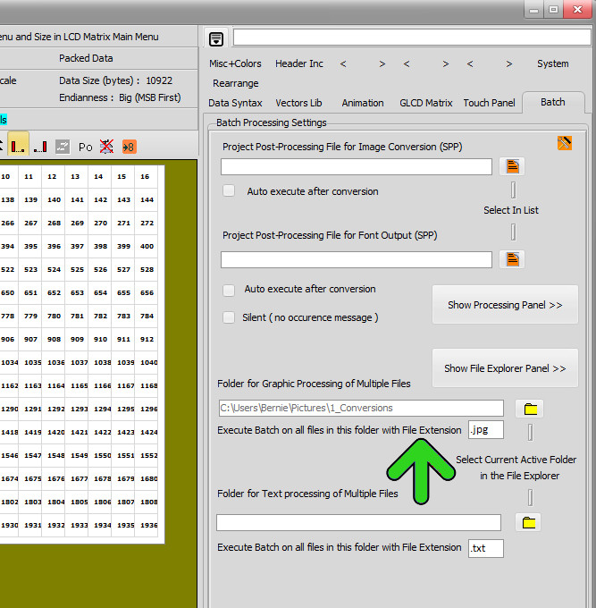
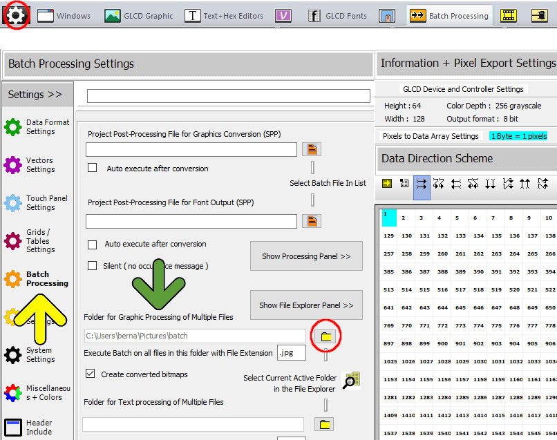
In the Configuration Settings Panel (yellow arrow), prepare the settings (green arrow)

The current selected folder in the File explorer, will be defined in the Folder field by clicking the yellow folder button (red circle) Then define the source Files extension as JPG or PNG or BMP …

If you want converted bitmaps then check then Create converted bitmaps checkbox.

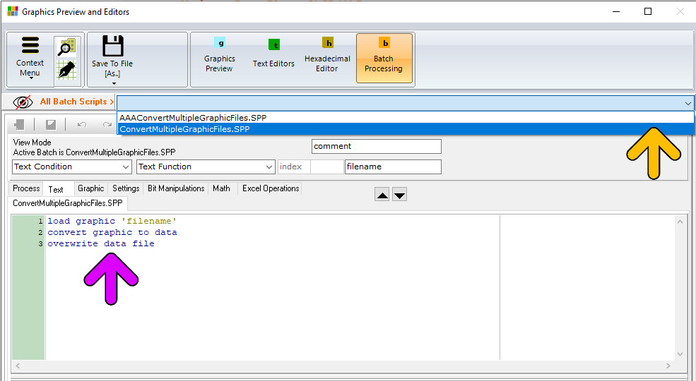
This Batch processing Program is preexists. Click at the right of the All Batch Scripts Bar (orange arrow) and select ConvertMultipleGraphicFiles.SPP.

The Batch program appears in the edit area (Purple arrow)

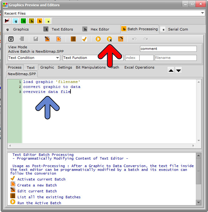
In the Batch Processing Main menu, you can Activate the current Batch (blue arrow) and see the activated batch Active batch = name.SPP

Run Batch Multiple will start the batch processing (green arrow)

Run the process and wait.

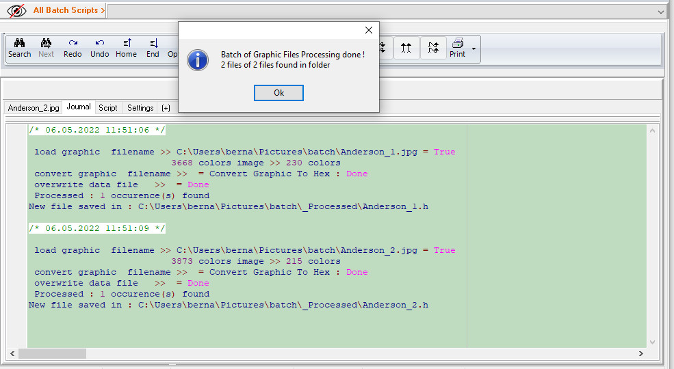
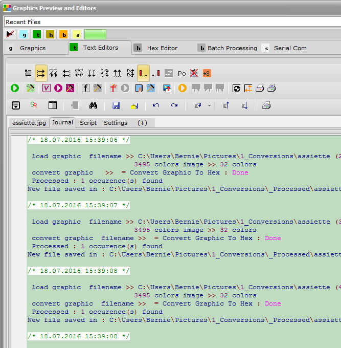
When the processing journal appears, the batch processing has been completed.

The output files can be found in the …\batch\_processed folder

Older Bitmap2LCD versions

A mouse right click inside the programming field will show you a pop up menu !

  • Do not forget to activate this batch ( check active processing batch is… label )
  • Define source folder of all the graphic files in the settings ( see 2nd screenshot below )
  • Check/modify the Work canvas size, in this example, all source bitmaps will be resized to canvas size !
  • Check/modify the normal data output format settings
  • Start the processing ( red arrow )
  • Read the processing report
  • bitmap2lcd graphic files batch

From Bitmap2LCD V3.7

Buttons have been moved to the the main Menu

bitmap2lcd-batch-processing-menu
  • Select the batch for multiple files processing in the configuration settings -> Batch Tab and define the currently active folder in the file explorer as the “Folder for Graphic Processing of Multiple Files” Folder.
  • The converted Output files will be saved during the process to the above defined source files folder + sub-folder \processed
  • Also check/modify the Graphic File Extension field. (green Arrow)
  • bitmap2lcd graphic files batch settings

At the end of the processing run, you can read the processing report as shown below.

In the example below, color bitmaps are converted to 16 level grayscale

bitmap2lcd graphic files batch report

Bitmap2LCD : Batch Programming

Bitmap2LCD is a tool for programming small Graphic LCDs in embedded systems and a programmable graphic and text processing tool.

From Bitmap2LCD V2.9 and upwards, article update V3.6h

Note : Additional Processing functions will be implemented in the future

Bitmap2LCD : Batch Programming

A batch program is a set of conditions, functions etc… one per line.

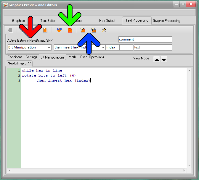
The program can’t be edited directly by writing texts. Any action must be made inside the field indicated by the red and green arrows. Cursor is a highlighted line. Cursor moves are made using keyboard up and down keys or by clicking on the destination program line.

  • Use the tabs to browse the group of basic functions ( Blue arrow )
  • Use the Comboboxes to select and program the condition/setting or function. ( red arrows ) In the Edit Mode, insert the selected function as next to the current cursor position with return key.
  • Use the Edit fields ( green arrow ) to edit a constant like an index (numeric), a text (chars) or a comment (chars)
  • Call the pop-up menu ( purple arrow ) by clicking the right mouse key inside the white program field.
  • Move up or down a program function with the up and down buttons ( gray arrow ) or use alternative CTRL+UP and CTRL+DOWN key combination
  • Next to the gray arrow, a label indicates the current View or Edit mode : A Batch can only be modified in Edit Mode

bitmap2lcd Batch Programming_2

Update V3.7c

Buttons have been moved into the main menu !

bitmap2lcd-batch-processing-menu

To start a batch processing, it must be active ( red arrow ) ( You can have many batch programs on disk to choose from )

Activating a batch can be made with a button ( green arrow ) or by clicking an item in the pop-up menu (Right Mouse click)

A batch processing can be started with two buttons : ( blue arrow ) A single processing (left side of blue arrow) or a processing on multiple files located in a defined folder (right side of blue arrow ). A processing can also be started in the Batch Processing main menu.

Batch Processing files ( .SPP  ) are always located in the defined Project Output Files folder. To view a list the batches on disk, click on the list batch button or use the pop up menu item.

Bitmap2LCD : Graphic Processing Functions

Bitmap2LCD is a tool for programming small Graphic LCDs in embedded systems and a programmable graphic and text processing tool.

From Bitmap2LCD V2.9 and upwards , article update V3.6h

Bitmap2LCD : Graphic Processing Functions

Note : Additional Processing functions will be implemented in the future


load graphic ‘filename’           

Loads the defined graphic defined under filename in the Graphics Library Folder into the Work Canvas, converts the graphic to the configured graphic mode. ( grayscale,color ) No directory allowed under ‘filename‘ !

For multiple graphic file processing , there must not be a filename defined :  ‘filename’

convert graphic to hex

Converts the work Canvas to a Data Array inside the Text Editor

overwrite text file

Saves or Overwrites (without prompt if already exists) the text file with the text Editor Content. Filename is the same as the graphic source file name with configured data file extension, and is saved in the defined output files folder.

For multiple file processing , the output files are saved in a subdirectory of the graphic files source folder


Bitmap2LCD : Introducing The Programmable Graphic Processing

Bitmap2LCD is a tool for programming small Graphic LCDs in embedded systems and a programmable graphic and text processing tool.

Bitmap2LCD : Introducing The Programmable Graphic Processing

From Bitmap2LCD V2.9 and up to V3.0, then obsolete

( from V3.0+ these functions have been moved inside the single batch processing feature

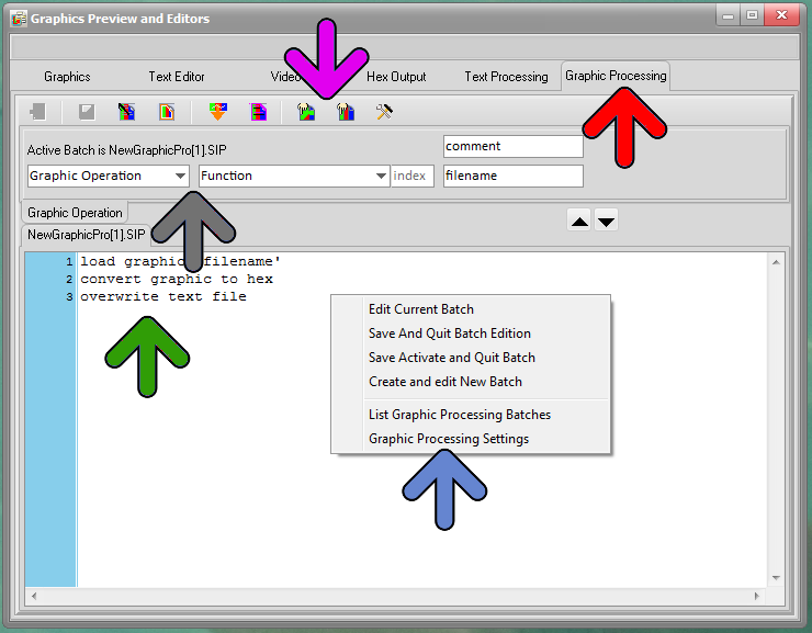
The Graphic Processing Panel can be found in the Graphics Preview and Editors Window, by clicking the Graphic Processing Tab (red arrow)

The program field (green arrow) can’t be directly edited as text : The selection of functions and the edition of values and characters can only be done in the programming panel (gray arrow)

In the bar of icons (purple arrow) and the pop-up menu (blue arrow) (accessible by a right click) , you can edit a batch, activate a batch, list all existing processing batches and select one, The two icons pointed by the purple arrow are the Processing Start buttons : The left one starts a single Processing Pass, the right one starts the processing on multiple files, located in a selected folder.

A Graphic Processing Batch file has a .SIP extension

Batch Graphic Processing_1


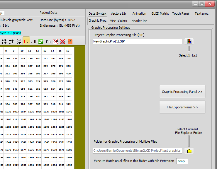
The graphic processing settings are located in the Settings Window Graphic Proc Tab

There are the fields to define the batch in the list (at the top) and the source folder where the multiple files to process are located and their graphic extension (for example .bmp)

Note : To define this source folder, first select the folder in the file explorer and then click the yellow button below. The output files of a multiple file processing batch will be saved in a sub folder of the defined folder.

If not programmatically modified, the current main settings like color/grayscale the data output format and other settings are active when running the processing.

Batch Graphic Processing_2