Category Archives: About Graphic LCD

About LED Back light driving methods

About LED Back light driving methods

( A Hantronix Application Note )

 LED Back Light Driving Methods

I. Introduction:
LED back lights on LCD modules are generally driven with a DC voltage through a
current limiting resistor. This simple approach is perfectly acceptable for most
applications. When the primary consideration is an extra bright display, the lowest
possible power consumption, or a back light that can be controlled over a very wide
brightness range another method is needed. The purpose of the paper is to describe this
method.

II. Description:
By using a pulse width modulation scheme several advantages can be realized over the
simple DC voltage method. The main advantage is in efficiency. The LED’s are pulsed
with a high current for a short period of time. For example consider the HDM16216L-7.
The nominal LED driving current for this display is 120 mA which produces a typical
brightness of 50 NIT. If, instead of a DC or constant current, we apply5 times the current,
600ma, for 1/5 of the time, the average current is the same, 120ma. See Figure #1. The
average brightness of the LED would also be the same if measured electronically. The
difference is in the perceived brightness

leddim1


The human eye has a certain amount of persistence. If exposed to a bright light the eye
will “remember” the light for a short period of time. This allows us to view a motion
picture or TV screen as a steady image when in fact it is flickering at 24 to 30 times a
second. When the LED is flashed on brightly for a short time and then turned off the eye
“remembers” the light at the high brightness level. The result is that the perceived
brightness of the back light is closer to the high pulsed brightness than to the lower DC
brightness.

This effect can be used to advantage in several ways. If the brightest possible back light is needed the display can be pulsed at a 1:4 on/off ratio with5 times the typical current. The pulse repetition frequency should be greater than 100Hz so the flickering is not perceptible to the eye but not greater than about 1kHz.

This technique can also be used to give a “normal” looking brightness level to the display
but at a lower average current to save power. The average power can be cut by a factor
of at least 50% to produce a given perceived brightness level. This can be a big advantage in battery operated equipment.

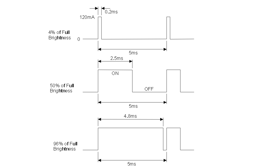
The third use of this method is to facilitate a wide range brightness control for the LED
back light. By varying the on/off ratio a very wide range of brightness can be achieved
while maintaining a very even appearing back light. See Figure #2. One can also very the
brightness by simply varying the DC current to the LED’s but at low current the individual
LED emitters start to become visible resulting in an uneven looking back light. To implement this technique the peak current should be set at the specified typical current for the display and the on/off ration of the pulses varied from near 100% on to near 0% on.

leddim2


Displaying Bitmap Images Easily on Small Graphic LCDs

Displaying Bitmap Images Easily on Small Graphic LCDs

Using the MCU as LCD Controller

In systems with relatively fast CPUs and small (quarter VGA or less) LCDs, there is no need for an LCD controller. The microcontroller (MCU) can do the job of the LCD controller on the side, refreshing the display in an interrupt service routine. The MCUs memory is used as video memory.

Advantages of this approach include the following:

– Very fast update of display possible.
– Eliminating the LCD controller (and its external RAM) reduces hardware costs.
– Simplified hardware design.

The disadvantage is that much of the available computation time is used
up. Depending on the MCU, this can be anything between 20 and almost 100 percent; with slower MPUs, it is really not possible at all.

Source Article

Factors to consider when evaluating a GLCD

Factors to consider when evaluating a GLCD

List of important factors to consider :

Resolution: The horizontal and vertical dot matrix sizes of the module expressed in pixels (e.g. 240×128).

Dot pitch: The distance between the centers of two adjacent pixels. The smaller the dot pitch size, the less granularity is present, resulting in a sharper image. Dot pitch may be the same both vertically and horizontally, or different (less common).

Viewing angle : LCD displays have a limited viewing angle. They lose contrast and become hard to read at some viewing angles and they have more contrast and are easier to read at others. The size of the viewing angle is determined by several factors, primarily the type of LCD fluid and the duty cycle. Because the viewing angle tends to be smaller than most people would like, a bias is designed into the module at the time it is manufactured. This means the nominal viewing angle is offset from the perpendicular by some amount. Several versions of the LCD module are then offered with this bias set to different angles or positions to accommodate as many applications as possible. The term “bias angle” is often used erroneously with the term “viewing angle”.

Response time: The minimum time necessary to change a pixel’s color or brightness. Check or compare the LCD controllers and their interface performances.

Interface : Parallel 8 bit Data bus, serial like SPI ?

Contrast Control : On chip generated and can be defined in the LCD controller’s registers or need of an external hardware circuitry like charge pump + DAC ?

Temperature Range : Need of an extended temperature LCD module ?
The LCD Contrast is temperature sensitive.

Paging Scheme System : Are the pixels stored in the module embedded LCD Controller’s internal Ram in a horizontal or a vertical manner ? Checking and comparing the LCD controller data sheets first to fix the choice.

Software driver : Hardware implementation is one thing, but trying to consider investigating the internet about existing software modules or libraries for THIS particular Graphic LCD Controller, looking for existing drivers in C language will bring you a lot !

What is a GUI ?

What is a GUI ?

What is a GUI ?

A graphical user interface (GUI) is a type of user interface item that allows people to interact with programs in more ways than typing such as computers; hand-held devices such as MP3 Players, Portable Media Players or Gaming devices; household appliances and office equipment with images rather than text commands. A GUI offers graphical icons, and visual indicators, as opposed to text-based interfaces, typed command labels or text navigation to fully represent the information and actions available to a user. The actions are usually performed through direct manipulation of the graphical elements.

The term GUI is historically restricted to the scope of two-dimensional display screens with display resolutions capable of describing generic information, in the tradition of the computer science research at Palo Alto Research Center (PARC). The term GUI earlier might have been applicable to other high-resolution types of interfaces that are non-generic, such as video games, or not restricted to flat screens, like volumetric displays.

More and source =>
Wikipedia Article

Memory space requirements for LCD

Memory space requirements for LCD

For the LCD panel, the required memory can be calculated using the following equation:

Required Memory =  ( Horizontal Resolution x Vertical Resolution /8* ) x bpp

( * For 8 bit data memory )

The memory requirements shown here are the minimum amounts required. In some cases, space for additional frame buffers may be needed.
For instance, it is common for some graphics software to maintain two separate frame buffers.
This enables the display of one frame buffer while another frame buffer is being updated by the software.

Panel Resolution—Total Pixels—Color Depth—-Required Memory for
—————————————————-bpp———Single Frame Buffer

320×240 (QVGA)—-76.8K———16bpp———53.6 KB
—————————————–12bpp———115.2 KB
—————————————–8bpp———–76.8 KB
—————————————–4bpp———–38.4 KB
—————————————–1bpp———–9.6 KB

128×128———-16.384K———-16bpp———32.768 KB
——————————————12bpp———24.576 KB
——————————————8bpp——— 16.384 KB
——————————————1bpp——— 2.048 KB

84×48————-4.032K———-16bpp———-8.064 KB
—————————————-12bpp———-6.048 KB
—————————————-8bpp ———–4.032 KB

Alphanumeric (character) LCD module vs. Graphic LCD Module

Alphanumeric (character) LCD module vs Graphic LCD Module

Comparing Font :

A large number of alphanumeric LCD modules are based on the Hitachi HD44780 which contains a character generator.
All the Character LCD controllers have their own fixed font and character generator. (CGROM)

Many of the newer Graphic LCD controllers have their own internal font. So you can send it as text, and it will draw it for you.
(For example the good old T6963C is having an internal CGROM) Others do not, in which case you will need to send a bitmap of the character to the display.
The size of the library code that drives the actual device is obviously larger for the Graphics chip, and an external font uses program memory.
If you are tight for memory space then choose the type with an internal font and smallest library.

About Color LCD Displays

About Color LCD Displays

In colour LCDs each individual pixel is divided into three cells, or subpixels, which are coloured red, green, and blue, respectively, by additional filters (pigment filters, dye filters and metal oxide filters). Each subpixel can be controlled independently to yield thousands or millions of possible colours for each pixel. CRT monitors employ a similar ‘subpixel’ structures via phosphors, although the electron beam employed in CRTs do not hit exact subpixels.

Color Interface Pixel Format

Most important thing in interfacing color LCD is to know how color is defined to a given pixel. The NXP PCF 8833 Color LCD controller for example, has three modes of color interface pixel format.

12 bit per pixel pixel format

RRRRGGGG 4 bits red and 4 bits green 1st pixel
BBBBRRRR 4 bits blue 1st pixel and 4 bits red 2nd pixel
GGGGBBBB 4 bits green and 4 bits blue 2nd pixel

8 bit per pixel pixel format

RRRGGGBB 3 bits red, 3 bits green and 2 bits blue

16 bit per pixel pixel format

RRRRRGGG 5 bits red and 3 bits green 1st pixel
GGGBBBBB 3 bits red and 5 bits blue 1st pixel

Temperature compensation for LCD Display

Temperature compensation for LCD Display

An application Note

The optimal contrast setting for LCD displays varies with ambient temperature. For most
applications this variation in contrast is tolerable over the “normal” temperature range of 0°C to +50°C. Most LCD modules are available with an extended temperature range option
which allows the display to operate from-20°C to +70°C. The changes in contrast are NOT
usually tolerable over this wide a range of temperatures, which means a way of adjusting the contrast voltage as the ambient temperature changes must be provided

PDF =>
http://www.newhavendisplay.com/app_notes/Temperature_Compensation.pdf

About the OLED LCD display technology

About the OLED LCD display technology

:: General Informations collected on the Internet , moved from the bitmap2lcd forum ::

An organic light emitting diode (OLED), also light emitting polymer (LEP) and organic electro luminescence (OEL), is a light-emitting diode (LED) whose emissive electroluminescent layer is composed of a film of organic compounds. The layer usually contains a polymer substance that allows suitable organic compounds to be deposited. They are deposited in rows and columns onto a flat carrier by a simple “printing” process. The resulting matrix of pixels can emit light of different colors.

Such systems can be used in television screens, computer monitors, small, portable system screens such as cell phones and PDAs, advertising, information and indication. OLEDs can also be used in light sources for general space illumination, and large-area light-emitting elements. OLEDs typically emit less light per area than inorganic solid-state based LEDs which are usually designed for use as point-light sources.

A significant advantage of OLED displays over traditional liquid crystal displays (LCDs) is that OLEDs do not require a backlight to function. Thus, they can display true black color, draw far less power, and can be much thinner and lighter than an LCD panel. OLED displays also naturally achieve much higher contrast ratio than LCD monitors.

Advantages of the OLED technology

The radically different manufacturing process of OLEDs lends itself to many advantages over flat-panel displays made with LCD technology. Since OLEDs can be printed onto any suitable substrate using an inkjet printer or even screen printing technologies, they can theoretically have a significantly lower cost than LCDs or plasma displays. Printing OLEDs onto flexible substrates opens the door to new applications such as roll-up displays and displays embedded in fabrics or clothing.

OLEDs enable a greater range of colors, gamut, brightness, contrast (both dynamic range and static) and viewing angle than LCDs because OLED pixels directly emit light. OLED pixel colors appear correct and unshifted, even as the viewing angle approaches 90 degrees from normal. LCDs use a backlight and cannot show true black, while an off OLED element produces no light and consumes no power. Energy is also wasted in LCDs because they require polarizers that filter out about half of the light emitted by the backlight. Additionally, color filters in most color LCDs filter out two-thirds of the light; technology to separate backlight colors by diffraction has not been widely adopted.

OLEDs also have a faster response time than standard LCD screens. Whereas the fastest LCD displays currently have a 2ms response time, an OLED can have less than 0.01ms response time. But due to limitations of the human eye, people won’t see a big difference with any video response time under 5 ms.

Disadvantages of the OLED technology
The biggest technical problem for OLEDs is the limited lifetime of the organic materials. In particular, blue OLEDs historically have had a lifetime of around 14,000 hours (five years at 8 hours a day) when used for flat-panel displays, which is lower than the typical lifetime of LCD, LED or PDP technology—each currently rated for about 60,000 hours, depending on manufacturer and model. However, some manufacturers of OLED displays claim to have come up with a way to solve this problem with a new technology to increase the lifespan of OLED displays, pushing their expected life past that of LCD displays.[45] A metal membrane helps deliver light from polymers in the substrate throughout the glass surface more efficiently than current OLEDs. The result is the same picture quality with half the brightness and a doubling of the screen’s expected life.

In 2007, experimental PLEDs were created which can sustain 400 cd/m² of luminance for over 198,000 hours for green OLEDs and 62,000 hours for blue OLEDs.

The intrusion of water into displays can damage or destroy the organic materials. Therefore, improved sealing processes are important for practical manufacturing and may limit the longevity of more flexible displays.

URL ==>
Source : Wikipedia