Tag Archives: 16 grey levels

Grayscale GLCD controller support : 4,16 and 32 gray levels

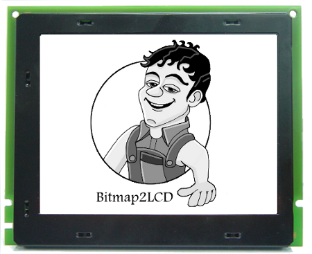
Bitmap2LCD is a tool for programming small Graphic LCDs in embedded systems.

Since V2.3 and upwards, Bitmap2LCD supports the 4,16 and 32 level grayscale controllers. ( Newly implemented are the 4 and 32 gray levels capability )

Color images and pictures can be imported and converted to 4, 16 and 32 gray levels into the work canvas. The software tool then generates the pixel data array in the selected arrangment, 2, 4 or 5 bits per pixel.

Here’s a list of grayscale LCD controllers, featuring 4, 16 and 32 gray levels.


Grayscale LCD Controllers

4 Gray Levels (2bpp)


S6B0741 128×129 Samsung


KS0741 128×129 Samsung


HT1647 64×16 Holtek


ST7541 128×129 Sitronix


ST7571 128×129 Sitronix


ST7586S 384×160 Sitronix


UPD16686 128×128 NEC


UPD16498 128×128 NEC


UPD16488A 128×92 NEC


HD66750 128×128 Hitachi


HD66421 160×100 Hitachi


EM65100 69 x101 Elan Microelectronics Corp


NJU6680 128×128 New Japan Radio


NJU6682 160×132 New Japan Radio


RA8806 320X240 Raio Technology


16 Gray Levels (4bpp)


EM65101 128×160 Elan Microelectronics Corp


SSD1322 480×120 Solomon Systech


SSD1325 128×80 Solomon Systech


SSD1326 256×32 Solomon Systech


SSD1327 128×128 Solomon Systech


32 Gray Levels (5bpp)


ST7529 255×160 Sitronix
 

Bitmap to GLCD Hex file >> Output settings

Bitmap2LCD is a tool for programming small Graphic LCDs in embedded systems.

Go to the Main Settings (v2.5 +):

bitmap2lcd settings

From V2.5, the below settings can also be found on the file explorer window, outputs tab : there’s a button at the top right to hide or show this toolbar.


fig 1. Hex file output settings buttons [ Bitmap2LCD from V2.0 upwards ]


Bitmap2LCD is a universal programming tool for converting bitmaps/images to GLCD for most graphic LCD controllers. (Monochrome,Grayscale, and Color ->[Color from V2.0] )

The software converts the bitmap and generates a hexadecimal file according to the previously defined user settings.

Here’s a short description of the available settings :

The hexadecimal output format can be selected with a series of buttons located in the output panel (fig 1.)

Description of the settings:

  • The choice of 8 different vertical or horizontal pagings ( the buttons with the arrows ) , your choice depends of the GLCD controller which is built in your LCD module. ( Please refer to the GLCD controller datasheet )
  • Most significant bit is first or is last (Data bit 7) — or in other words the data endianness.
  • Byte nibble swap On/Off, for example for 16 gray level grayscale mode for Sitronix ST7528 controller compatibility. ( In the case of 2 pixel per data byte, 4 bit per pixel data, gray levels )
  • Negative or positive output setting
  • GLCD zero corner selection (Corner where the conversion starts)
  • Output File Header Editor , (A small script to configure Hex file header)
  • Enable/Disable of the Output Data for compression for monochrome GLCD.
  • Enable/Disable 6 or 8 bit Data byte wide output for T693C Controller

As the converted output can just contain a part of the display size, there are other selectable options (not on fig1.)

  • Enable/disable X,Y area coordinate data insertion in the Hex ouptut file
  • Enable/disable area size data insertion in the Hex output file

These configuration settings are saved when you quit the application and restored on application launch. These settings are also a part of the project specific configuration.

Find other available settings in this topic.